General Operation
40 AX500 Motor Controller User’s Manual Version 1.9b. June 1, 2007
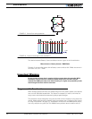
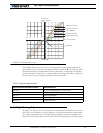
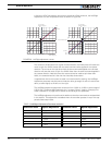
The relation between Battery Current and Motor current is given in the formula below:
Motor Current = Battery Current / PWM Ratio
Example: If the controller reports 10A of battery current while at 10% PWM, the current in
the motor is 10 / 0.1 = 100A.
Important Warning
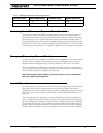
Do not connect a motor that is rated at a higher current than the controller. While
the battery current will never exceed the preset Amps limit, that limit may be
reached at a PWM cycle lower than 100% resulting in a higher and potentially unsafe
level through the motor and the controller.
Programmable Acceleration
When changing speed command, the AX500 will go from the present speed to the desired
one at a user selectable acceleration. This feature is necessary in order to minimize the
surge current and mechanical stress during abrupt speed changes.
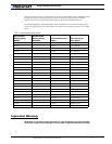
This parameter can be changed by using the controller’s front switches or using serial com-
mands. When configuring the controller using the switches (see “Configuring the Control-
ler using the Switches” on page 171), acceleration can be one of 6 available preset values,
from very soft(0) to very quick (6). The AX500’s factory default value is medium soft (2).
Off
On
Vbat
Motor
FIGURE 17. Current flow during operation
Off
I mot
Avg
I bat
Avg
On
FIGURE 18. Instant and average current waveforms


