


AX500 Motor Controller User’s Manual 55
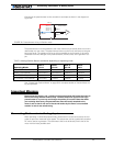
Connecting Tachometer to Analog Inputs
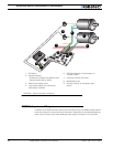
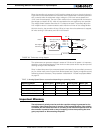
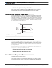
Connecting the potentiometer to the controller is as simple as shown in the diagram on
Figure 28.
The potentiometer must be attached to the motor frame so that its body does not move in
relationship with the motor. The potentiometer axle must be firmly connected to the gear
box output shaft. The gearbox must be as tight as possible so that rotation of the motor
translates into direct changes to the potentiometers, without slack, at the gearbox’s out-
put.
See “Closed Loop Position Mode” on page 63 for complete details on Position Mode wir-
ing and operation.
Important Warning
Beware that the wrong + and - polarity on the potentiometer will cause the motor to
turn in the wrong direction and not stop. The best method to figure out the right
potentiometer is try one way and change the polarity if incorrect. Note that while
you are doing these tests, the potentiometer must be loosely attached to the
motor’s axle so that it will not be forced and broken by the motor’s uncontrolled
rotation in case it was wired wrong.
Connecting Tachometer to Analog Inputs
When operating in closed loop speed mode, tachometers must be connected to the con-
troller to report the measured motor speed. The tachometer can be a good quality brushed
DC motor used as a generator. The tachometer shaft must be directly tied to that of the
motor with the least possible slack.
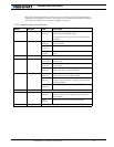
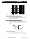
TABLE 9. Analog Position Sensor connection depending on operating mode
Operating Mode
Ana 1
pin 11
Ana2
pin 10
Ana 3
pin 12
Ana 4
pin 8
RC or RS232 - Dual Channel Position 1 Position 2 Unused Unused
Analog - Dual Channel Command 1 Command 2 Position 1 Position 2
RC or RS232 - Single Channel Position Unused Unused Unused
RC or RS232 - Dual Channel Command Unused Position Unused
47kOhm
10kOhm
47kOhm
10kOhm
Internal Resistors
and Converter
Ana 1: 11
Ana 2: 10
Ana 3: 12
Ana 4: 8
+5V 14
Ground 5
A/D
FIGURE 28. Potentiometer wiring in Position mode