


AX500 Quick Start
16 AX500 Motor Controller User’s Manual Version 1.9b. June 1, 2007
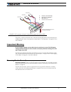
Important Warning
The controller includes large capacitors. When connecting the Motor Power Cables,
a spark will be generated at the connection point. This is a normal occurrence and
should be expected.
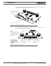
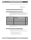
Connecting to the 15-pin Connector
The controller’s I/O are located on it’s standard 15-pin D-Sub Connector. The functions of
some pins varies depending on controller model and operating mode. Pin assignment is
found in the table below.
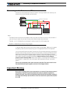
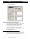
Connecting the R/C Radio
Connect the R/C adapter cables to the controller on one side and to two or three channels
on the R/C receiver on the other side. If present, the third channel is for activating the
accessory outputs and is optional.
When operating the controller in “Separate” mode, the wire labelled Ch1 controls Motor1,
and the wire labelled Ch2 controls Motor2.
When operating the controller in “Mixed” mode, Ch1 is used to set the robot’s speed and
direction, while Ch2 is used for steering.
See “R/C Operation” on page 81 of the User’s Manual for a more complete discussion on
R/C commands, calibration and other options.
Pin
Signal
RC Mode RS232 Mode Analog Mode
1 100mA Digital Output C (same as pin 9)
2TxData
3 RC Ch1 RxData Unused
4 RC Ch 2 Digital Input F
5 Ground Out
6 Unused
7 Unused
8 Digital Input E and Analog Input 4
9 100mA Digital Output C (same as pin 1)
10 Analog Input 2
11 Analog Input 1
12 Analog Input 3
13 Ground Out
14 +5V Out (100mA max.)
15 Emergency Stop or Invert Switch input