


Connecting Sensors and Actuators to Input/Outputs
50 AX500 Motor Controller User’s Manual Version 1.9b. June 1, 2007
I/O List and Pin Assignment
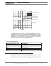
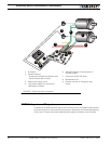
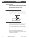
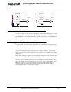
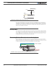
The figure and table below lists all the inputs and outputs that are available on the AX500.
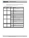
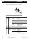
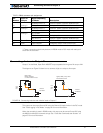
TABLE 8. DB15 connector pin assignment
Pin
Number
Input or
Output
Signal depending
on Mode Description
1 and 9 Output Output C 100mA Accessory Output C
2Output
R/C: Data Out RS232 Data Logging Output
RS232: Data Out RS232 Data Out
Analog: Data Out RS232 Data Logging Output
3 Input
R/C: Ch 1 R/C radio Channel 1 pulses
RS232: Data In RS232 Data In (from PC/MCU)
Analog: Unused Unused
4 Input
R/C: Ch 2 R/C radio Channel 2 pulses
RS232/Analog: Input F Digital Input F readable RS232 mode
Dead man switch activation
5 and 13 Power Out Ground Controller ground (-)
6 Unused Unused Unused
7 Unused Unused Unused
8 Digital In
and Analog
In
R/C: Ch 3 R/C radio Channel 3 pulses
RS232: Input E / Ana in
4
Accessory input E
Dead man Switch Input
Activate Output C
Analog Input 4
Ana: Input E / Ana in 4 Accessory input E
Dead man Switch Input
Activate Output C
Channel 2 speed or position feedback input
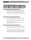
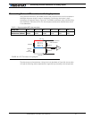
Pin1
8
15
9
FIGURE 22. Controller’s DB15 connector pin numbering