


R/C Operation
86 AX500 Motor Controller User’s Manual Version 1.9b. June 1, 2007
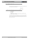
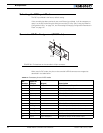
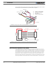
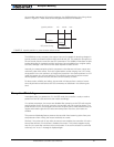
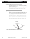
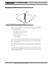
to the controller does not inject power into the controller. The figure below show the cable
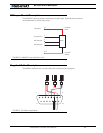
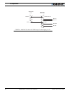
with the loop cut. Figure 56 shows the equivalent electrical diagram.
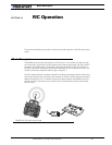
Operating the Controller in R/C mode
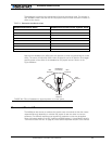
In this operating mode, the AX500 will accept commands from a Radio Control receiver
used for R/C models remote controls. The speed or position information is communicated
to the AX500 by the width of a pulse from the R/C receiver: a pulse width of 1.0 millisec-
ond indicates the minimum joystick position and 2.0 milliseconds indicates the maximum
joystick position. When the joystick is in the center position, the pulse should be 1.5ms.
Note that the real pulse-length to joystick-position numbers that are generated by your R/C
radio may be different than the ideal 1.0ms to 2.0ms discussed above. To make sure that
8
9
15
Pin 1
Channel 1
Channel 2
3: Channel 1 Command Pulses
4: Channel 2 Command Pulses
6: Radio battery (-) Ground
7: Radio battery (+)
8: Channel 3 Command Pulses
Channel 3:
Cut red loop
FIGURE 55. Wiring when receiver is powered by its own separate battery
Controller
Power
R/C Radio Power
Cut
Radio
Battery
R/C Radio
R/C Channel 1
R/C Channel 2
R/C Radio Ground
Controller
Ground
R/C Channel 3
14
3
7
8
6
5-13
4
MCU
FIGURE 56. Electrical diagram for connection to independently powered RC radio