


AX500 Motor Controller User’s Manual 27
Controller Powering Schemes
The table below shows the state of the controller depending on the voltage applied to
Vcon and Vmot.
Controller Powering Schemes
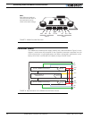
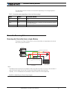
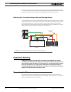
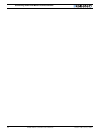
Powering the Controller from a single Battery
The diagram on Figure 19 show how to wire the controller to a single battery circuit and
how to turn power On and Off.
TABLE 2. Controller status depending on Vcon and Vmot voltage
VCon VMot Controller Status
Off Off Off
Off 5-24V Off
8-24V Off Controller MCU is On. Controller will communicate but motors
cannot be activated
8-24V 5-24V Controller is On and motors are activated
12V to 24V
Motor Battery
Power on/off switch
-
+
+
-
Motor1
Motor2
Controller
Fuse
VMot
VMot
M1+
M1-
VCon
GND
GND
GND
M2+
M2-
Notes:
- The Battery Power connection are doubled in order to provide the maximum current to the controller. If
only one motor is used, only one set of motor power cables needs to be connected.
- Typically, 1 or 2 x 12V batteries are connected in series to reach 12 or 24V respectively.
FIGURE 9. AX500 Electrical Power Wiring Diagram