


AX500 Motor Controller User’s Manual 47
AX500 Connections
SECTION 6 Connecting
Sensors and
Actuators to
Input/Outputs
This section describes the various inputs and outputs and provides guidance on how to
connect sensors, actuators or other accessories to them.
AX500 Connections
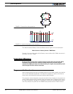
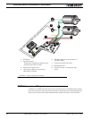
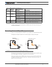
The AX500 uses a set of power wires (located on the back of the unit) and a DB15 connec-
tor for all necessary connections. The diagram on the figure below shows a typical wiring
diagram of a mobile robot using the AX500 controller.
The wires are used for connection to the batteries and motors and will typically carry large
current loads. Details on the controller’s power wiring can be found at “Connecting Power
and Motors to the Controller” on page 25
The DB15 connector is used for all low-voltage, low-current connections to the Radio,
Microcontroller, sensors and accessories. This section covers only the connections to sen-
sors and actuators.
For information on how to connect the R/C radio or the RS232 port, see “R/C Operation”
on page 81 and “Serial (RS-232) Controls and Operation” on page 101.