


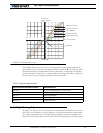

AX500 Motor Controller User’s Manual 39
Battery Current vs. Motor Current
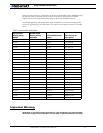
The numbers in the table are the max Amps allowed by the controller at a given tempera-
ture point. If the Amps limit is manually set to a lower value, then the controller will limit
the current to the lowest of the manual and temperature-adjusted max values.
This capability ensures that the controller will be able to work safely with practically all
motor types and will adjust itself automatically for the various load and environmental con-
ditions. The time it takes for the heat sink’s temperature to rise depends on the current
output, ambient temperature, and available air flow (natural or forced).
Note that the measured temperature is measured on the PCB near the Power Transistors
and will rise and fall faster than the outside surface.
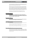
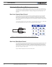
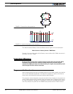
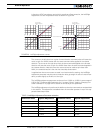
Battery Current vs. Motor Current
The controller measures and limits the current that flows from the battery. Current that
flows through the motor is typically higher. This counter-intuitive phenomenon is due to the
“flyback” current in the motor’s inductance. In some cases, the motor current can be
extremely high, causing heat and potentially damage while battery current appears low or
reasonable.
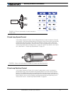
The motor’s power is controlled by varying the On/Off duty cycle of the battery voltage
16,000 times per second to the motor from 0% (motor off) to 100 (motor on). Because of
the flyback effect, during the Off time current continues to flow at nearly the same peak -
and not the average - level as during the On time. At low PWM ratios, the peak current -
and therefore motor current - can be very high as shown in Figure 18, “Instant and average
current waveforms,” on page 40.
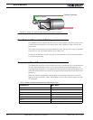
The relation between Battery Current and Motor current is given in the formula below:
Motor Current = Battery Current / PWM ratio
Example: If the controller reports 10A of battery current while at 10% PWM, the current in
the motor is 10 / 0.1 = 100A.