


Serial (RS-232) Controls and Operation
120 AX500 Motor Controller User’s Manual Version 1.9b. June 1, 2007
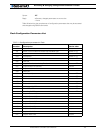
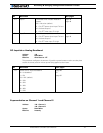
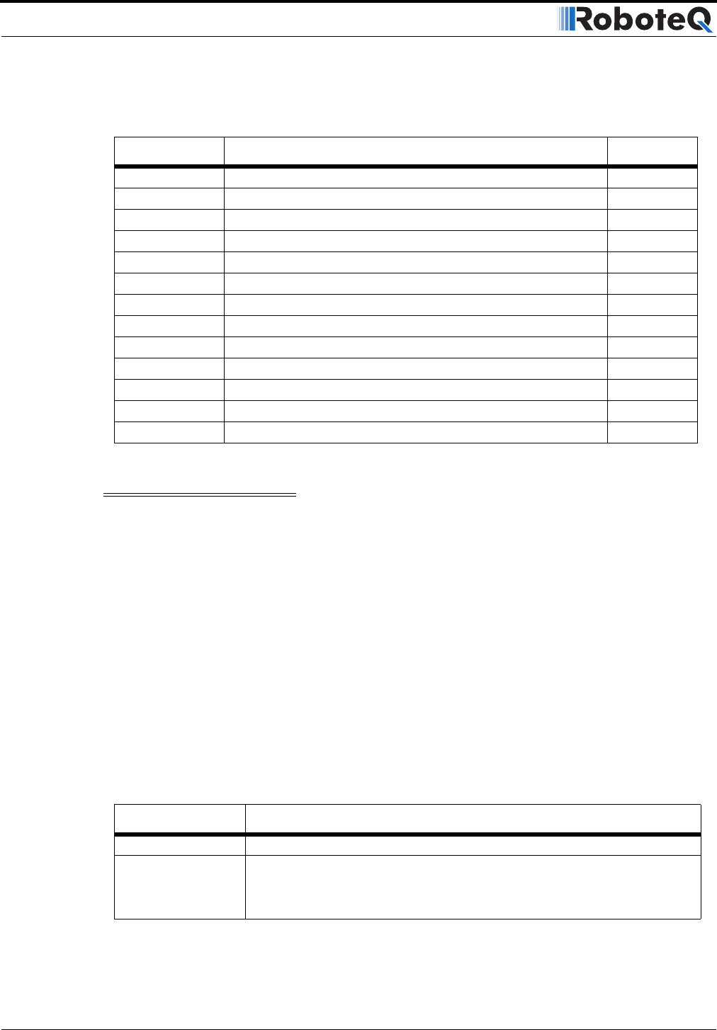
The table below lists the available parameters
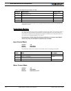
Important Notice:
Do not write in the locations marked as Read Only. Doing so my cause Controller
malfunction.
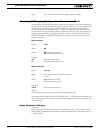
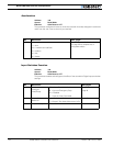
Operating Modes Registers
Address: ^80 - Channel 1
^81 - Channel 2
Access: Read/Write
Effective: Instantly
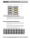
Modifying the bits in the Operating Mode registers will change the controller’s operating
modes on-the fly. Changes take effect at the controller’s next 16ms iteration loop. After
reset, these bits get initialized according to the configuration contained in Flash.
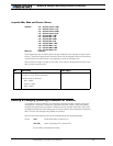
Values are in Hexadecimal.Example: 00000101 = Hex 05
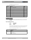
TABLE 19. Runtime R/W Parameters list
Location Function R/W
^80 Channel 1 Operating Modes R/W
^81 Channel 2 Operating Modes R/W
^82 PID Proportional gain 1 R/W
^83 PID Proportional gain 2 R/W
^84 PID Integral gain 1 R/W
^85 PID Integral gain 2 R/W
^86 PID Differential gain 1 R/W
^87 PID Differential gain 2 R/W
^88 PWM frequency R/W
^89 Controller Status R Only
^8A Controller Model R Only
^8B Current Amps limit 1 R Only
^8C Current Amps limit 2 R Only
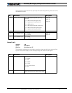
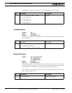
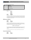
TABLE 20. Operating Modes Register Definition
Bit Function
7 to 3 Not Used
2 0: Open Loop
1: Closed Loop
(when in Speed Mode)