


AX500 Motor Controller User’s Manual 15
Connecting to the Batteries and Motors
Connecting to the Batteries and Motors
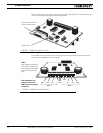
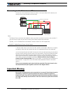
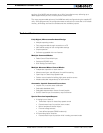
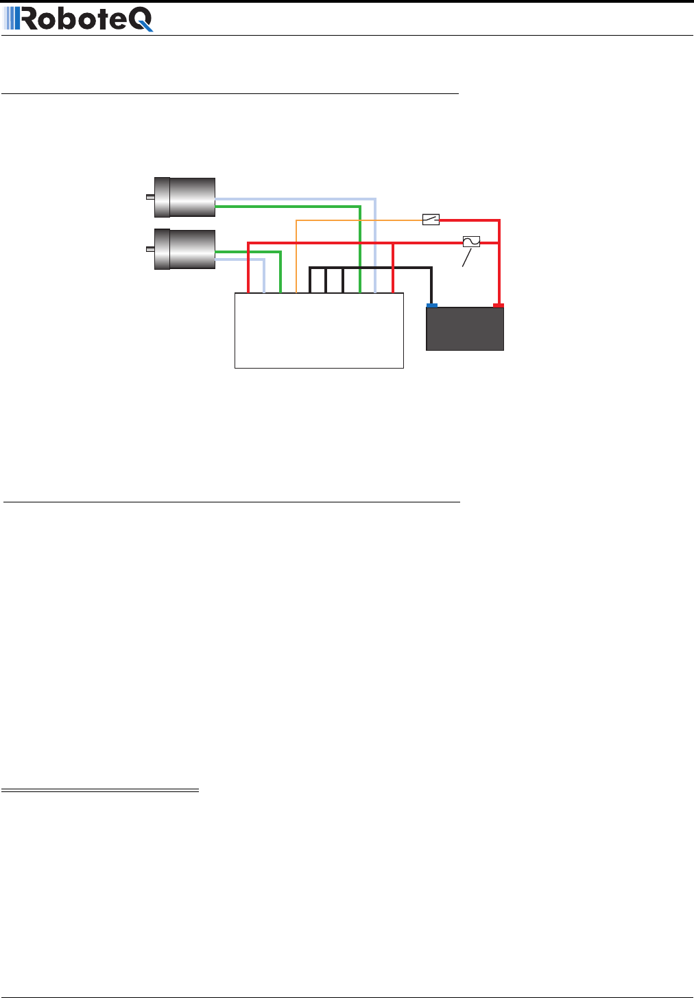
Connection to the batteries and motors is shown in the figure below and is done by con-
necting wires to the controller’s terminal strip.
1- Connect each motor to one of the two M+ and M- terminal pairs. Make sure to respect
the polarity, otherwise the motor(s) may spin in the opposite direction than expected
two of the three Ground terminals2- Connect the VCon terminal (powering the controller’s
internal circuits) through a power switch to the main battery. Connect the VMot terminals
(powering the output drivers) directly and permanently to the positive battery terminal.
VCon may be connected to a separate battery to ensure that the controller stays alive even
as the battery powering the Motors discharges. Motors will turn only if voltage is
present on both VCon and VMot. Refer to the chapter “Connecting Power and Motors to
the Controller” on page 25 for more information about batteries and other connection
options.
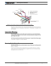
The two are connected to each other inside the controller. The same is true for the.
You should wire each pair together as shown in the diagram above.
Important Warning
Do not rely on cutting power to the controller for it to turn off if the Power Control is
left floating. If motors are spinning because the robot is pushed are pushed or
because of inertia, they will act as generators and will turn the controller, possibly in
an unsafe state. Always use the switch on the VCon terminal to power the controller
On or Off.
12V to 24V
Motor Battery
Power on/off switch
-
+
+
-
Motor1
Motor2
Controller
Fuse
VMot
VMot
M1+
M1-
VCon
GND
GND
GND
M2+
M2-
Notes:
- The Battery Power connection are doubled in order to provide the maximum current to the controller. If
only one motor is used, only one set of motor power cables needs to be connected.
- Typically, 1 or 2 x 12V batteries are connected in series to reach 12 or 24V respectively.
FIGURE 3. AX500 Electrical Power Wiring Diagram