


Closed Loop Position Mode
64 AX500 Motor Controller User’s Manual Version 1.9b. June 1, 2007
Position Sensor Selection
The AX500 may be used with the following kind of sensors:
• Potentiometers
• Hall effect angular sensors
The first two are used to generate an analog voltage ranging from 0V to 5V depending on
their position. They will report an absolute position information at all times.
Sensor Mounting
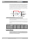
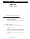
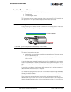
Proper mounting of the sensor is critical for an effective and accurate position mode opera-
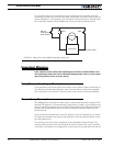
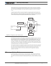
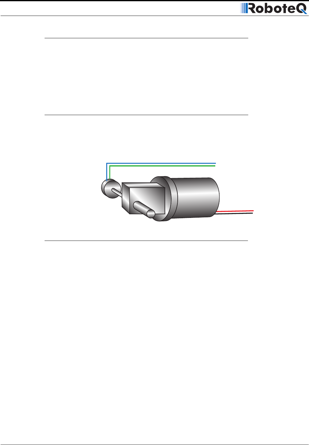
tion. Figure 35 shows a typical motor, gear box, and sensor assembly.
The sensor is composed of two parts:
• a body which must be physically attached to a non-moving part of the motor assem-
bly or the robot chassis, and
• an axle which must be physically connected to the rotating part of the motor you
wish to position.
A gear box is necessary to greatly increase the torque of the assembly. It is also necessary
to slow down the motion so that the controller has the time to perform the position control
algorithm. If the gearing ratio is too high, however, the positioning mode will be very slug-
gish.
A good ratio should be such that the output shaft rotates at 1 to 10 rotations per second
(60 to 600 RPM) when the motor is at full speed.
The mechanical coupling between the motor and the sensor must be as tight as possible.
If the gear box is loose, the positioning will not be accurate and will be unstable, potentially
causing the motor to oscillate.
Some sensor, such as potentiometers, have a limited rotation range of typically 270
degrees (3/4 of a turn), which will in turn limit the mechanical motion of the motor/potenti-
ometer assembly. Consider using a multi-turn potentiometer as long as it is mounted in a
Position Sensor
Gear box
Position Feedback
FIGURE 35. Typical motor/potentiometer assembly in Position Mode