


Connecting Power and Motors to the Controller
28 AX500 Motor Controller User’s Manual Version 1.9b. June 1, 2007
There is no need to insert a separate switch on Power cables, although for safety reasons,
it is highly recommended that a way of quickly disconnecting the Motor Power be provided
in the case of loss of control and all of the AX500 safety features fail to activate.
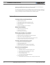
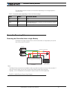
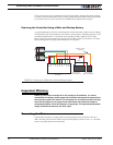
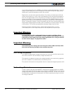
Powering the Controller Using a Main and Backup Battery
In typical applications, the main motor batteries will get eventually weaker and the voltage
will drop below the level needed for the internal microcomputer to properly operate. For all
professional applications it is therefore recommended to add a separate 12V (to 24V)
power supply to ensure proper powering of the controller under any conditions. This dual
battery configuration is highly recommended in 12V systems.
Important Warning
Unless you can ensure a steady 8V to 24V voltage in all conditions, it is recom-
mended that the battery used to power the controller’s electronics be separate from
the one used to power the motors. This is because it is very likely that the motor bat-
teries will be subject to very large current loads which may cause the voltage to
eventually dip below 12V as the batteries’ charge drops. The separate backup power
supply should be connected to the VCon input.
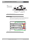
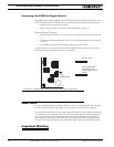
Connecting the Motors
Connecting the motors is simply done by connecting each motor terminal to the M1+
(M2+) and M1- (M2-) terminal. Which motor terminal goes to which of the + or - controller
output is typically determined empirically.
12V to 24V
Motor Battery
12V to 24V
Backup Battery
Power on/off
switch
-
+
+
-
Motor1
Motor2
Controller
Fuse
VMot
VMot
M1+
M1-
VCon
GND
GND
GND
M2+
M2-
FIGURE 10. Powering the AX500 with a Main and Backup Supply