


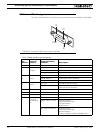


Connecting Sensors and Actuators to Input/Outputs
54 AX500 Motor Controller User’s Manual Version 1.9b. June 1, 2007
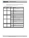
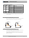
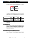
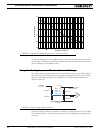
The status of the EStop/Inv can be read at all times in the RS232 mode with the ?i com-
mand string. The controller will respond with three sets of 2 digit numbers. The status of
the ES/Inv Input is contained in the last set of numbers and may be 00 to indicate an Off
state, or 01 to indicate an On state.
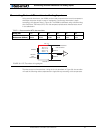
Analog Inputs
The controller has 4 Analog Inputs that can be used to connect position, speed, tempera-
ture, voltage or most other types of analog sensors. These inputs can be read at any time
using the ?p query for Analog inputs 1 and 2 and the ?r query for Inputs 3 and 4. The fol-
lowing section show the various uses for these inputs.
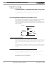
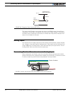
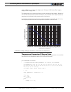
Connecting Position Potentiometers to Analog Inputs
When configured in the Position mode, the controller’s analog inputs are used to obtain
position information from a potentiometer coupled to the motor axle. This feature is useful
in order to create very powerful servos as proposed in the figure below:
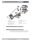
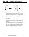
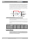
10kOhm
AX2500 Internal
Buffer and Resistor
Input
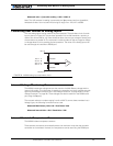
EStop/Inv 15
+5V 14
Ground 5
FIGURE 26. Emergency Stop / Invert switch wiring
Potentiometer
Gear box
Position Feedback
FIGURE 27. Motor and potentiometer assembly for position servo operation