


AX500 Motor Controller User’s Manual 139
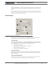
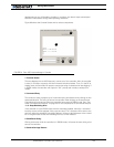
Running the Motors
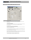
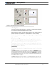
1- Run/Stop Button
This button will cause the PC to send the run commands to the controller and will update
the screen with measurements received from the controller.
When the program is running, the button’s caption changes to “Stop”. Pressing it again will
stop the motors and halt the exchange of data between the PC and the controller.
If another tab is selected while the program is running, the program will stop as if the Stop
button was pressed.
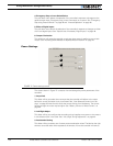
2- Motor Power setting
This sub-frame contains a slider and several buttons. Moving the slider in any direction
away from the middle (stop) position will cause a power command to be issued to the con-
troller. The value of the command is shown in the text field below the slider.
The stop button will cause the slider to return to the middle (stop) position and a 0-value
command to be sent to the controller. The + and ++ buttons will cause the slider to move
by 1 or 10 power positions respectively.
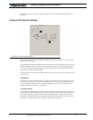
3- Measurement
These series of fields display the various operating parameters reported in real-time by the
controller:
The Amps field reports the current measured at each channel. The Peak Amps field will
store the highest measured Amp value from the moment the program began or from the
time at which the peak was reset using the Clr Peak button. Motor Amps is a calculated
estimated value based on the batter amps and the current power level. See “Battery Cur-
rent vs. Motor Current” on page 39.
The Power field displays the power level that is actually being applied to the motor. This
value is directly related to the motor command except during current limitation, in which
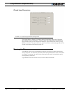
1
2
3
FIGURE 80. Motor exercising and monitoring screen
4
6
5
7
8