


AX500 Quick Start
18 AX500 Motor Controller User’s Manual Version 1.9b. June 1, 2007
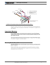
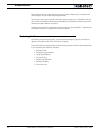
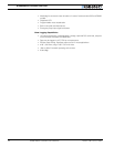
The status LED will start flashing a pattern to indicate the mode in which the controller is
in:
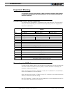
Default Controller Configuration
Version 1.9b of the AX500 software is configured with the factory defaults shown in the
table below. Although Roboteq strives to keep the same parameters and values from one
version to the next, changes may occur from one revision to the next. Make sure that you
have the matching manual and software versions. These may be retrieved from the
Roboteq web site.
Any one of the parameters listed in Table 1, and others not listed, can easily be changed
either using the PC with the Roboteq Configuration Utility. See “Using the Roborun Config-
uration Utility” on page 131.
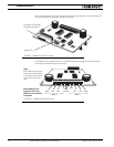
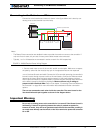
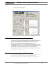
Connecting the controller to your PC using Roborun
Connecting the controller to your PC is not necessary for basic R/C operation. However, it
is a very simple procedure that is useful for the following purposes:
• to Read and Set the programmable parameters with a user-friendly graphical inter-
face
• to obtain the controller’s software revision and date
• to send precise commands to the motors
• to read and plot real-time current consumption value
• Save captured parameters onto disk for later analysis
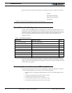
TABLE 1. AX500 Default Settings
Parameter Default Values Letter
Input Command mode: (0) = R/C Radio mode I
Motor Control mode (0) = Separate A, B, speed control, open loop C
Amp limit (5) = 13.125A A
Acceleration (2) = medium-slow S
Input switch function (3) = no action U
Joystick Deadband (2) = 16% d
Exponentiation on channel 1 (0) = Linear (no exponentiation) E
Exponentiation on channel 2 (0) = Linear (no exponentiation) F
Left / Right Adjust (7) = no adjustment L
RC Mode
RS232 Mode No Watchdog
RS232 Mode with Watchdog
Analog Mode
FIGURE 5. Status LED Flashing pattern during normal operation