


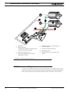

Connecting Sensors and Actuators to Input/Outputs
52 AX500 Motor Controller User’s Manual Version 1.9b. June 1, 2007
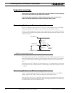
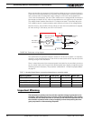
Important warning:
This output is unprotected. If your load draws more than 100mA, permanent damage
will occur to the power transistor inside the controller.
Overvoltage spikes induced by switching inductive loads, such as solenoids or
relays, will destroy the transistor unless a protection diode is used.
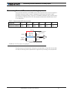
Connecting Switches or Devices to Input E
Input E is a general purpose, digital input. This input is only available when in the RS232
and Analog modes. In R/C mode, this line is used as the radio channel 3 input.
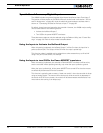
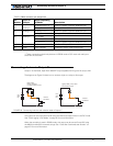
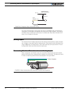
Input E is a high impedance input with a pull-up resistor built into the controller. Therefore
it will report an On state if unconnected, and a simple switch as shown on Figure 24 is nec-
essary to activate it.
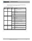
The status of Input E can be read in the RS232 mode with the ?i command string. The con-
troller will respond with three sets of 2 digit numbers. The status of Input E is contained in
the first set of numbers and may be 00 to indicate an Off state, or 01 to indicate an On
state.
Remember that InputE is shared with the Analog Input 4. If an analog sensor is connected,
the controller will return a Digital value of 0 if the voltage is lower than 0.5V and a value of
1 if higher
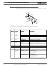
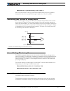
Connecting Switches or Devices to Input F
Input F is a general purpose digital input. This input is only active when in the RS232 or
Analog modes. In R/C mode, this line is used as the radio channel 2 input.
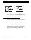
When left open, Input F is in an undefined stage. As shown in the figure below, a pull down
or pull up resistor must be inserted when used with a single pole switch. The resistor may
be omitted when used with a dual pole switch.
50kOhm
50kOhm
+5V Out 14
10kOhm
Internal
Buffer
Input E 8
Ground 5
FIGURE 24. Switch wirings to Input E