


Connecting Sensors and Actuators to Input/Outputs
48 AX500 Motor Controller User’s Manual Version 1.9b. June 1, 2007
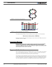
AX500’s Inputs and Outputs
In addition to the RS232 and R/C channel communication lines, the AX500 includes several
inputs and outputs for various sensors and actuators. Depending on the selected operating
mode, some of these I/Os provide feedback and/or safety information to the controller.
5
6
7
9
8
4
3
1
2
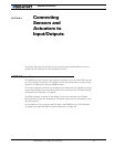
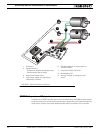
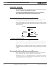
1- DC Motors
2- Optional sensors:
- Tachometers (Closed loop Speed mode)
- Potentiometers (Servo mode)
3- Motor Power supply wires
4- Logic Power supply wire (connected
optionally)5- Controller
6- R/C Radio Receiver, microcomputer, or
wireless modem
7- Command: RS-232, R/C Pulse
8- Miscellaneous I/O
9- Running Inverted, or emergency stop
switch
FIGURE 21. Typical controller connections
3