


AX500 Motor Controller User’s Manual 83
R/C Input Circuit Description
R/C Input Circuit Description
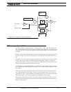
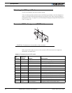
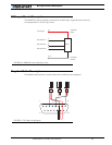
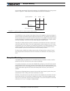
The AX500 R/C inputs are directly connected to the MCU logic. Figure 50 shows an electri-
cal representation of the R/C input circuit.
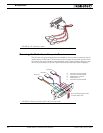
Supplied Cable Description
The AX500 is delivered with a custom cable with the following wiring diagram:
14
3
8
5-13
4
MCU
R/C Channel 1
R/C Channel 2
R/C Channel 3
Controller
Ground
Controller
Power
+5V Output
FIGURE 50. AX500 R/C Input equivalent circuit
1
8
9
15
1 2 3
FIGURE 51. RC Cable wiring diagram