


Closed Loop Speed Mode
74 AX500 Motor Controller User’s Manual Version 1.9b. June 1, 2007
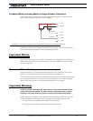
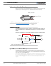
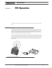
Tachometer or Encoder Mounting
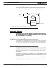
Proper mounting of the speed sensor is critical for an effective and accurate speed mode
operation. Figure 1 shows a typical motor and tachometer or encoder assembly.
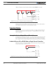
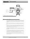
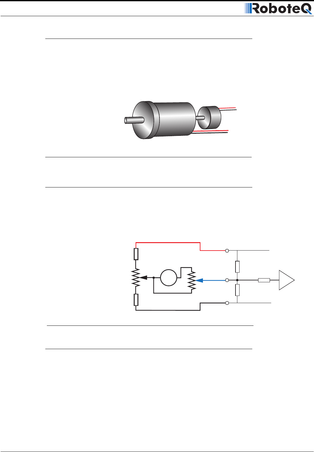
Tachometer wiring
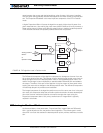
The tachometer must be wired so that it creates a voltage at the controller’s analog input
that is proportional to rotation speed: 0V at full reverse, +5V at full forward, and 0 when
stopped.
Connecting the tachometer to the controller is as simple as shown in the diagram below.
Speed Sensor and Motor Polarity
The tachometer or encoder polarity (i.e. which rotation direction produces a positive of
negative speed information) is related to the motor’s rotation speed and the direction the
motor turns when power is applied to it.
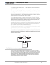
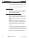
In the Closed Loop Speed mode, the controller compares the actual speed, as measured
by the tachometer, to the desired speed. If the motor is not at the desired speed and direc-
tion, the controller will apply power to the motor so that it turns faster or slower, until
reached.
P iti F db k
FIGURE 43. Motor and speed sensor assembly needed for Close Loop Speed mode
Speed feedbackSpeed feedback
Analog Tachometer
47kOhm
10kOhm
47kOhm
1kOhm
Max Speed Adjust
10kOhm pot
Zero Adjust
100 Ohm pot
1kOhm
Internal Resistors
and Converter
+5V 14
Ground 5
A/D
Ta c h
Ana 1: 11
Ana 2: 10
Ana 3: 12
Ana 4: 8
FIGURE 44. Tachometer wiring diagram