AX500 Motor Controller User’s Manual 141
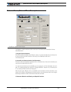
Running the Motors
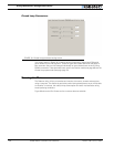
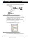
A timer is provided to keep track of time while running the motors. An additional set of but-
tons and displays are provided to operate a data logger. The data logger is fully described in
the section that follows.
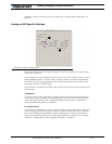
8- Joystick Enable
Enable and configure a joystick.
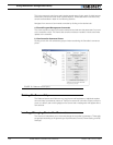
Logging Data to Disk
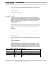
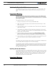
While running the motors, it is possible to have Roborun capture all the parameters that
were displayed on the various fields and charts and save them to disk. The log function is
capable of recording 32,000 complete sets of parameters, which adds up to approximately
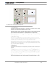
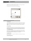
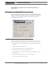
30 minutes of recording time. The figure below details the buttons and check boxes
needed to operate this function.
1- Log Check Box
When checked, Roborun will capture all the parameters and save them in local RAM. The
data is not saved to disk until the “Save to Disk” button is pressed. Data is being captured
for as long as the program is in the Run mode, whether or not a motor command is
applied.
2- Clear Log
This button can be pressed at any time to clear the local RAM from its content. Clearing
the log also has the effect of resetting the timer.
3- Log Fill Status
This gray text box indicates whether the local RAM log is empty, full or in-between.
4- Reset Timer button
The timer automatically runs when the Run button is pressed and data is being exchanged
with the controller, regardless of whether or not logging is activated. This button resets the
timer.
5- Save Log to Disk button
Pressing this button will prompt the user to select a filename and location where to copy
the logged data. The file format is a regular text file with each parameter saved one after
the other, separated by a coma. The file extension automatically defaults to .csv (coma
separated values) so that the data can be imported directly into Microsoft Excel. The first
line of the save file contains the Header names. Each following line contains a complete
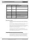
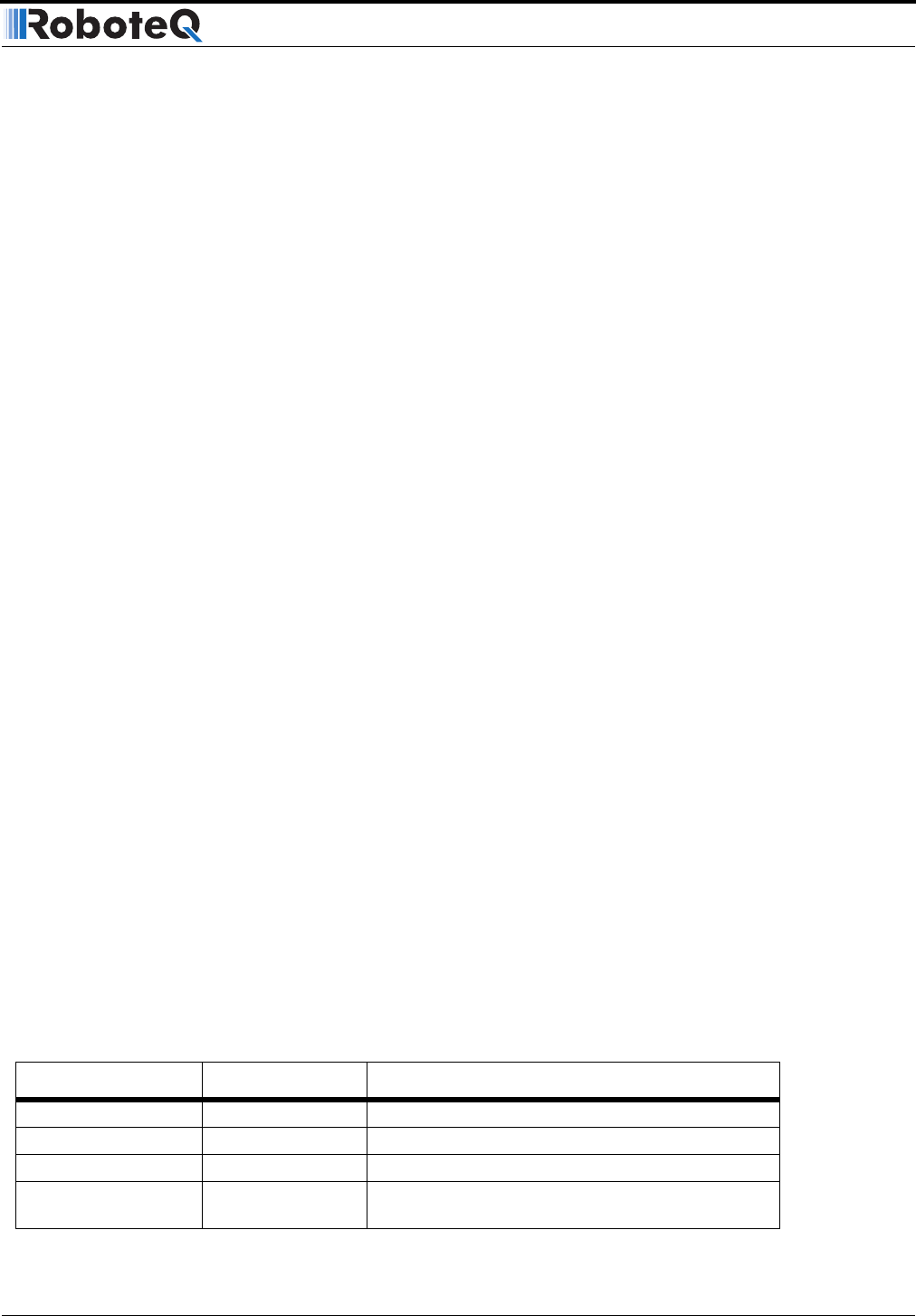
set of parameters. The Header name, order and parameter definition is shown in Table 25:
TABLE 25. Logged parameters order, type and definition
Parameter Header Data type/range Measured Parameter
Seconds Integer Timer value expressed in seconds
Command1 -127 to +127 Command applied to channel 1
Command2 -127 to +127 Command applied to channel 2
Power1 0 to 127 Amount of power applied to the output stage of chan-
nel 1


