


AX500 Motor Controller User’s Manual 67
Sensor and Motor Polarity
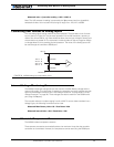
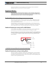
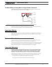
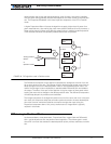
Feedback Wiring in Analog Mode on Single Channel Controllers
When the controller is configured in Analog mode, the analog input 1 is used for com-
mands while the analog input 4 is used for feedback.
Analog inputs 3 and 4 have different characteristics than inputs 1 and 2, and so require a
lower resistance potentiometer in order to guarantee accuracy.
Important Notice
This wiring is also the one to use when the controller is in Analog mode but switched to
RS232 after reset using the method discussed in “Entering RS232 from R/C or Analog
mode” on page 105
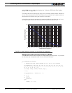
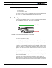
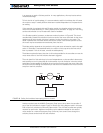
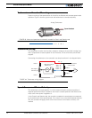
Sensor and Motor Polarity
The sensor polarity (i.e. which rotation end produces 0 or 5V) is related to the motor’s
polarity (i.e. which direction the motor turns when power is applied to it).
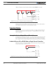
In the Position mode, the controller compares the actual position, as measured by the sen-
sor, to the desired position. If the motor is not at that position, the controller will apply
power to the motor so that it turns towards that destination until reached.
Important Warning:
If there is a polarity mismatch, the motor will turn in the wrong direction and the
position will never be reached. The motor will turn continuously with no way of
stopping it other than cutting the power or hitting the Emergency Stop button.
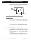
Determining the right polarity is best done experimentally using the Roborun utility (see
“Using the Roborun Configuration Utility” on page 131) and following these steps:
1. Disconnect the controller’s Motor Power (Vmot terminals).
2. Configure the controller in Position Mode using the PC utility.
2k 2k - 10k
10 Ana2
14 +5V
5 Ground
Command
Feedback
11 Ana1
8 Ana4*
12 Ana3*
FIGURE 39. Pot wiring on Single Channel controllers (SC version) and Analog Command