AX500 Motor Controller User’s Manual 79
Diagnostic LED
SECTION 9 Normal and
Fault Condition
LED Messages
This section discusses the meaning of the various messages and codes that may be dis-
played on the LED display during normal operation and fault conditions.
Diagnostic LED
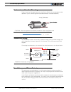
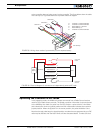
The AX500 features a single diagnostic LED which helps determine the controller’s operat-
ing mode and signal a few fault conditions. The LED is located near the edge of the board,
next to he 15-pin connector.
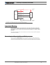
Normal Operation Flashing Pattern
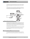
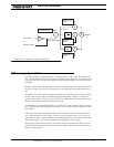
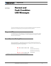
Upon normal operation, 1 second after power up, the LED will continuously flash one of
the patterns below to indicate the operating mode. A flashing LED is also an indication that
the controller’s processor is running normally.
RC Mode
RS232 Mode No Watchdog
RS232 Mode with Watchdog
Analog Mode
FIGURE 46. Status LED Flashing pattern during normal operation


