


40
1600XP Series Installation and Operation Manual
18. Communication Interfaces
18.1 Remote Contacts
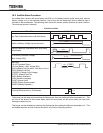
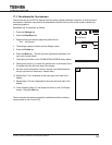
The remote contacts interface is provided as a set of solid state switching devices. The switches are
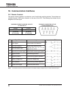
available through a DB9 male connector on the rear of the UPS. The following chart shows the pin
assignment for each signal.
MAXIMUM CURRENT CARRYING CAPACITY
OF THE SWITCH
DB9 MALE CONNECTOR OUTLINE
(FACING CONNECTOR)
Voltage Current
48 Vdc peak 70 mA peak
30 Vac rms
(42 Vac peak)
50 mA rms
(70 mA peak)
Pin Signal Function Logic In the UPS
1 Fault Signal Closed when fault detected
2 UPS stop common
Backup stop when the level
changes from Low (-3 to -15 V) to
High (+3 to +15 V)
3 UPS stop signal input
4 Normal input power supply Closed with normal supply power
5 Signal common Common signal return
6 Bypass operation Closed during bypass operation
7 Battery voltage drop Closed at voltage drop
8 UPS operation Closed during inverter operation
9 Power failure signal Closed at power failure
NOTE: Pin switches are shown in their inactive states. For example, if battery voltage is low, pin 7 will be connected to pin 5.