


49
1600XP Series Installation and Operation Manual
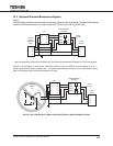
23. UPS Protection System
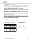
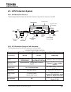
23.1 UPS Protection Devices
The following schematic shows the electrical locations of the protection devices on the UPS.
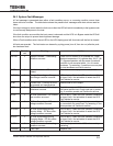
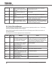
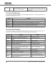
23.2 UPS Protection Devices Fault Response
The following charts show the UPS response to common faults.
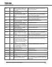
UPS FAULT PROTECTION FUNCTIONS
Protection Item Output Overvoltage Output Undervoltage Output Overload
LCD Message OUT-OV OUT-UV OVERLOAD
Cause
Control malfunction;
EEPROM error
Control malfunction;
Fuse opened; Load issue
Overload – Short circuit at load
Operation Mode
After Fault
Bypass operation – Chopper and inverter are
stopped
Inverter OL: Transfer to bypass;
Bypass OL: Inverter, chopper
stopped
Audible Alarm Yes – Continuous buzzer
See Audible Alarm Functions on
page 33
Visible Alarm Red Fault LED on
Inverter OL: Fault lamp off
Bypass OL: Fault lamp on
Relay Contact
Alarm
Fault relay closed
Bypass relay closed
Fault relay open;
Inverter OL: Bypass relay closed
Bypass OL: Bypass relay open
Auto-retransfer No
Inverter OL: Yes if bypass is OK
Bypass OL: No
Input
Abnormal
Low Battery
Level
Overheating
Overcurrent
Current Limit
Overload
Overvoltage/
Undervoltage
Output
Power
Line Filter Inverter
*Static Switch
Isolation
Transformer
Input
Power
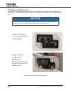
Input
Fuse
Power Flow
Bypass
* Switches are
solid state
devices.
MCCB
Output
Fuse
Surge
Absorber
Batteries
+
–
Rectier/
Chopper
Negative
Bus
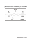
Optional
TVSS