B-21
1600XP Series Installation and Operation Manual
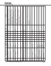
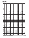
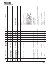
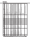
572-16Battery Cabinet 2 Current
offset Calibration
BC2 Tot I Ocali - - R R/W R/W Range: -1000 – 1000
572-17Clear Battery Cabinet 2
Disconnect Warning
Clr BC2 DNC Wrn R/W R/W R/W R/W R/W
752-18Constant Current Mode
Charger Reference BC2
CC Mode Chg Ref - - R R/W R/W Range: 750 – 1024
572-19Constant Voltage Mode
Charger Reference BC2
CV Mode Chg Ref - - R R/W R/W Range: 540 – 1024
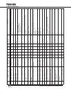
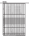
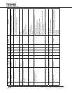
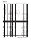
601 System Temperature
Control PCB’s I2C Device
System(CTL)
Temp
R R R R R 0 Thermostat on control PCB.
Units: °C
602 Battery Temperature Battery Temp R R R R R 0 Thermistor attached to the case of battery tray.
Units: °C
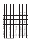
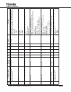
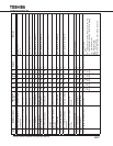
608 Current State of UPS Current State R R R R R 0: Shutdown [show Shutdown]
1: Initial Charge [show Shutdown]
2: Boostup [show Shutdown]
3: Normal (Online) [show Online]
4: Backup [show Backup]
5: Batttery Test [show Battery Test]
6: Bypass Normal [show Bypass]
7: Bypass Init [show Bypass]
8: Bypass Shutdown [show Bypass]
9: Startup [show Startup]
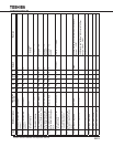
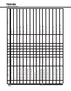
609 Operation Mode Transition
State Requested
Requested State R/W R/W R/W R/W R/W 1: Shutdown Request
2: Bypass Request
3: Online Request
4: Battery Test Request
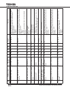
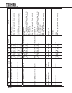
610 Operation Mode Transition
Timer
Timed Operation R/W R/W R/W R/W R/W 0 Sec The timer upon whose expiration a mode transition will
be attempted by the system.
Range: 0 – 800
Units: Sec
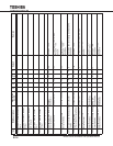
611 EPO Contact State EPO Status R R R R R Report of EPO input contact status.
0: Open
1: Closed
612 UPS Faults Faults R/W R/W R/W R/W R/W Only accept zero to clear Fault bit map
Item Brief Description
Description
On lCD
U A D
Svc/
QC
F Default Remark


