


A3
1600XP Series Installation and Operation Manual
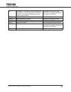
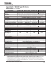
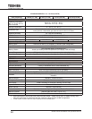
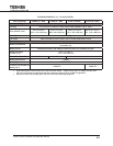
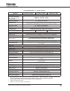
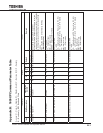
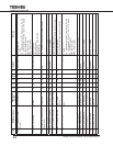
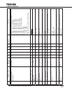
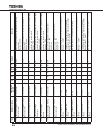
STANDARD MODELS: 3.6 – 10 KVA (CONT’D)
Unit (Capacity) 3.6kVA (3.1 kW)
1
6 kVA (5.1 kW)
1
8 kVA (6.8 kW)
1
10 kVA (8.5 kW)
1
Mechanical Design
Topology Unit enclosure is made from sheet metal meeting NEMA1 and UL Type 1
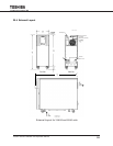
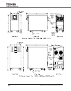
Size (HxWxD) (max)
22.1x 10 x 34 in.
(561 x 254 x 864 mm)
27.5 x 10 x 34 in.
(699 x 254 x 864 mm)
28.4x 13 x 34.9 in.
(721 x 330 x 886 mm)
28.4x 13 x 34.9 in.
(721 x 330 x 886 mm)
Paint System Powder coating
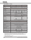
Fan Panel
2
Panel mounted on back of UPS to allow for easy replacement of fans
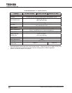
Battery System
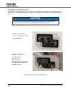
Battery Replacement
Slide out battery packs accessible from front of UPS. Factory or authorized service center
serviceable only.
Battery Packs Designed for battery acid leakage containment with six (6) batteries per pack
Battery Pack Size
(HxWxD) max.
5.0 x 7.3 x 19.0 in.
(127 x 185 x 483 mm)
Battery Pack Quantity 2 3 4
Battery Manufacturer YUASA
Battery Type REW45-12FR
Toshiba’s Part Number for
Battery Pack
51896-FS 60995-FS
1. Input/output gures rated for 240 volts unless otherwise stated. Output ratings given for 0.85PF are only valid
when the input voltage is greater than 204 volts; otherwise, ratings given for 0.70PF are applicable.
2. Remove all sources of main AC power and wait ve minutes before replacing fans.