


TOSHIBA
12 - 2
INDEX (cont'd)
C (con't)
Clearances ................................................................................................................ 2-1
Coast stop ................................................................................................................ 7-2
Codes (regulatory) ................................................................................................................ 2-1
Color (cabinet) ................................................................................................................ 3-5
Command mode selection ....................................................................................................... 8-28, 9-25
Commercial power switching output .............................................................................................. 8-6
Communication selection.............................................................................................................. 8-24
Communication setting parameters ...................................................................................... 8-24 thru 8-25
Confirmation (wiring) ................................................................................................................ 2-3
Connection diagrams ........................................................................................................... 4-1 to 4-3
Continue mode for speeds #1 thru #15 ................................................................................. 8-19 thru 8-21
Control system ................................................................................................................ 3-4
Conveyor application parameters ................................................................................................. 8-26
Cooling fan control ............................................................................................................... 8-15
Cooling method ................................................................................................................ 3-4
CPU version ............................................................................................................... 8-30
Cumulative run timer alarm setting ............................................................................................... 8-15
Current level of stall protection ..................................................................................................... 8-14
Current units selection ............................................................................................................... 8-30
Cutout, keypad ............................................................................................................... 11-7
D
Dancer ............................................................................................................... 11-7
Data bits (number) ............................................................................................................... 8-24
DC injection braking start frequency ............................................................................................. 8-13
DC injection current ............................................................................................................... 8-13
DC injection time ............................................................................................................... 8-13
Deceleration time #1 ................................................................................................................ 8-1
Deceleration time #2 ................................................................................................................ 8-2
Delay time FL output ................................................................................................................ 8-6
Delay time LOW output ................................................................................................................ 8-6
Delay time OUT output ................................................................................................................ 8-6
Delay time RCH output ................................................................................................................ 8-5
Detection bandwidth Acc/Dec ........................................................................................................ 8-6
Detection level for low current ...................................................................................................... 8-14
Detection time for low current ....................................................................................................... 8-14
Detection time for undervoltage .................................................................................................... 8-14
Differential gain ............................................................................................................... 8-22
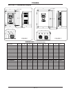
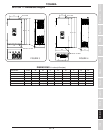
Dimensions ............................................................................................................... 11-1
Dimensions, keypad cutout........................................................................................................... 11-7
DIP switch SW1 ................................................................................................................ 5-3
Direction selection ................................................................................................................ 8-3
Display ................................................................................................................ 6-1
Disposal ................................................................................................................ 1-1
Drive time for speeds #1 thru #15 ........................................................................................... 8-19 to 8-21
Drooping control and amount........................................................................................................ 8-22
Dynamic braking ............................................................................................................... 8-13
E
EEPROM version ............................................................................................................... 8-30
Electronic thermal protection level #2 ............................................................................................ 8-2
EMC (European electro-magnetic compatibility) ............................................................................ 2-5
Emergency off ........................................................................................................... 8-13, 7-2