


TOSHIBA
4 - 7
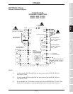
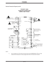
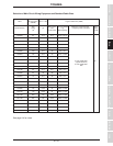
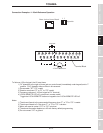
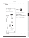
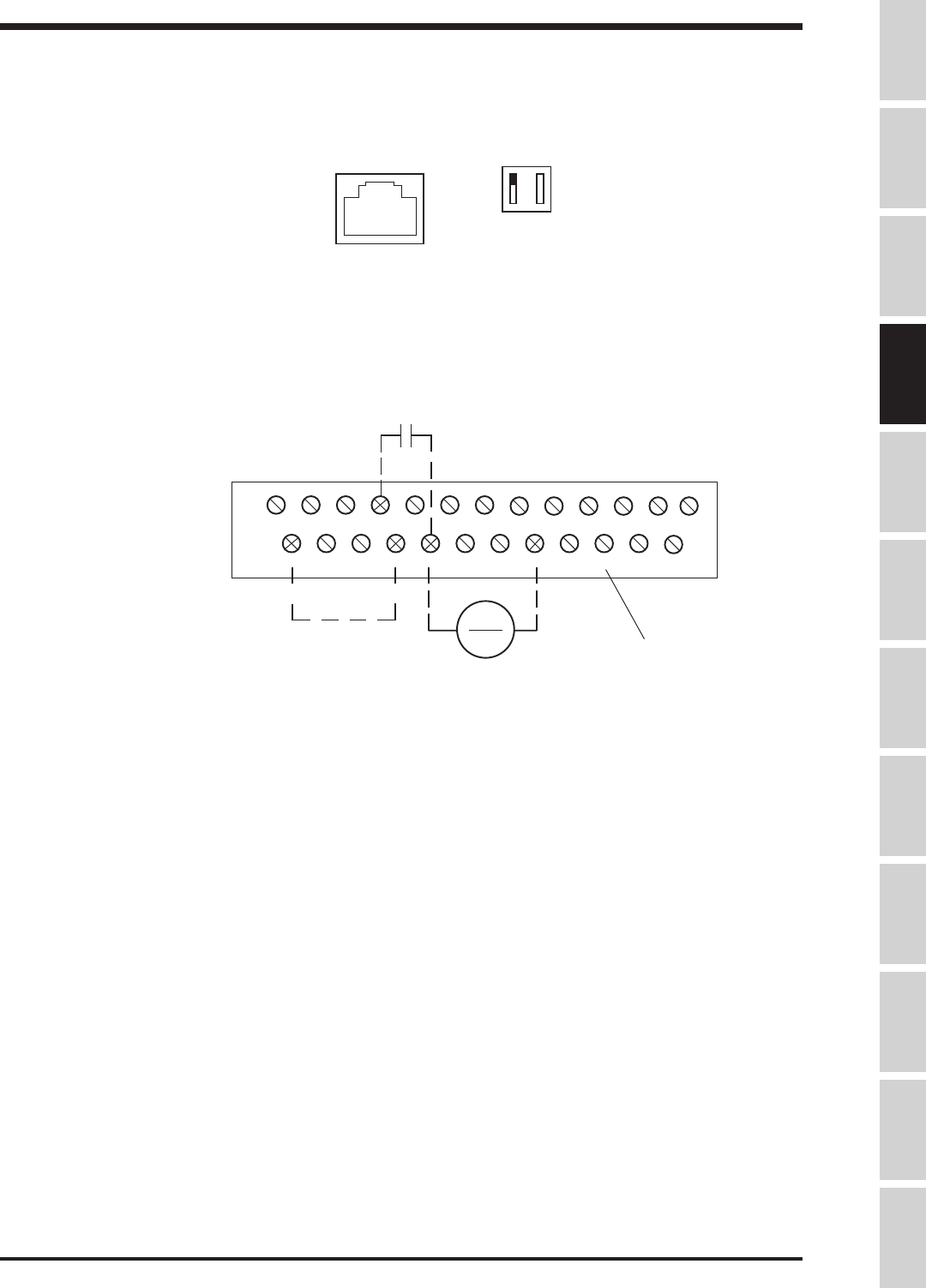
Terminal Block
ST FM AM CC CC RX PP IV FP FLC FLB FLA
P24 RES RR F R S1 S2 S3 S4
RCH
A
RCH
C
LOW
A
LOW
C
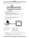
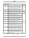
To follow a 4-20 mA signal, the H3 must have:
1) "IV" dipswitch to the right of phone jack on control board (immediately under keypad) set to "I"
position. "5/10" dipswitch has no effect in this scenario.
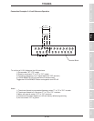
1) Drive enable ("ST"-"CC" made)
2) Direction command ("F" or "R" to "CC" made)
3) Frequency reference ( 4-20mA signal at "IV" terminal )
4) LOCAL/REMOTE LED off ( puts drive in remote mode)
Toggle the LOCAL/REMOTE button on keypad to turn LOCAL/REMOTE LED off.
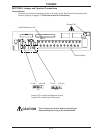
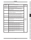
Notes:
1) The drive will accel to the commanded frequency when "F" or "R" to "CC" is made.
2) The drive will decel to 0.0 Hz when "F" or "R" to "CC" is broken.
3) Motor will coast to a stop if "ST" to "CC" is broken.
4) The above information applies to a H3 with factory default programming.
5) Do not connect "CC" to ground.
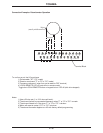
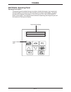
stop/start
I 5
V 10
Dipswitch
4-20 mA Reference
Phone Jack on Control Board
>
(+)
( - )
Connection Examples: 4 - 20mA Reference Operation
Specifications
Precautions
Wiring
JumpersPanelKeypadParametersProgrammingServiceDimensionsIndex Inspection