


TOSHIBA
9 - 16
Parameter Explanations (cont'd)
DYNAMIC BRAKING
(Feature not available in H3 drives above 30 horsepower)
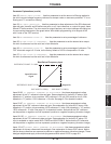
When a motor is mechanically forced to spin faster than the output frequency of the drive, the
motor acts as a generator. This regenerated energy forces current to flow into the drive's DC
bus. The bus capacitors will absorb some of the regenerative energy by charging and raising the
DC bus voltage. At high bus voltages, the drive can be programmed to fire the IGBT7 dynamic
braking transistor. This prevents a common drive fault, DC BUS OVERVOLTAGE. The dynamic
braking resistor, attached by the user to the "PA" and "PB" terminals, dissipates the bus energy
as heat when the IGBT7 fires. Two resistor values are of concern: resistance (ohms) and power
(watts). Insufficient resistance may lead to IGBT7 damage; too low of a wattage may result in
braking resistor damage from overheating.
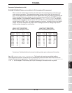
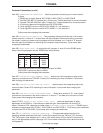
HEAVY DUTY RESISTORS LIGHT DUTY RESISTORS
WATTS: 300 watts per drive HP WATTS: 60 watts per drive HP
H3 H.D. H3 H.D. H3 L.D. H3 L.D.
Model Ohms Model Ohms Model Ohms Model Ohms
2035 35 4055 108 2035 150 4055 360
2055 28 4080 65 2055 90 4080 240
2080 20 4110 60 2080 61 4110 180
2110 12 4160 38 2110 45 4160 120
2160 7.0 4220 30 2160 30 4220 90
2220 6.0 4270 22 2220 23 4270 70
2270 5.0 4330 20 2270 18 4330 61
2330 4.0 2330 15
Contact your Toshiba distributor for dynamic braking resistor part numbers and information.
Item 145, OVERVOLTAGE STALL PROTECTION - This function is turned on as a default setting.
Overvoltage stall protection causes the drive to automatically extend the decel time when the DC bus
voltage increases due to regeneration. The value stored in DECELERATION TIME #1 / DECELERATION
TIME #2 is not changed. The drive may still trip on overvoltage if the decel time is very small.
Specifications
Precautions
Wiring
JumpersPanelKeypadParametersProgrammingServiceDimensionsIndex Inspection