


TOSHIBA
9 - 15
Parameter Explanations (cont'd)
Item 108, JOG RUN FREQUENCY - Use this parameter to set the run frequency during a jog. An accel
time of zero is used, so low jog frequencies of 5 Hz or less and light loads are recommended. For
information on jogging from the keypad, see page 7-1. For information on how to jog from the terminal
strip, see pages 8-9 and 9-9. During a jog, low speed, speed reach, and PID, functions do not operate.
Item 109, JOG STOP METHOD - This parameter determines the way a jog is stopped. If DC Injection is
selected, also adjust Item 146, DC INJECTION STARTING FREQUENCY, Item 147, DC INJECTION
CURRENT, and Item 148, DC INJECTION TIME. Jog is stopped by releasing the "RUN" key (when in
panel control), and by opening "F"-"CC" or "R"-"CC" (when in remote control).
Item 110, PRESET SPEED SELECTION - Enter the total number of preset speeds to be accessed.
Item 111, PRESET SPEED MODE ACTIVATION - If this parameter is set to "1", the corresponding preset
speeds' acc/dec time selection, volts per hertz pattern selection, and direction is determined by the setting
of PRESET SPEED #<1,2,3,4,5,6,7,8,9,10,11,12,13,14,or 15> OPERATING MODE (Items 113, 115,
117, etc.). Directions commanded by closing "F"-"CC" or "R"-"CC" are effectively ignored. If Item 111 is set
to "0", the direction is determined by the terminal strip.
Items 112, 114, 116, 118, 120, 122, 124, 126, 128, 130, 132, 134, 136, 138, 140, PRESET SPEED
#<1,2,3,4,5,6,7,8,9,10,11,12,13,14,or 15> FREQUENCY - Use this parameter to set preset speed
frequencies.
Items 113, 115, 117, 119, 121, 123, 125, 127, 129, 131, 133, 135, 137, 139, 141, PRESET SPEED
#<1,2,3,4,5,6,7,8,9,10,11,12,13,14,or 15> OPERATING MODE - Use this parameter to associate a
direction and ACCELERATION TIME #1 / DECELERATION TIME #1 or ACCELERATION TIME #2 /
DECELERATION TIME #2 with a preset speed. See Item 111.
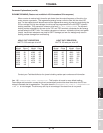
With default programming, the "S1", "S2", "S3", and "S4" terminals (see Items 45-48) are preset
speed selections via a binary implementation. Some examples:
"S4" to "CC" "S3" to "CC" "S2" to "CC" "S1" to "CC" Commanded Preset Speed #
open open open close 1
open open closed closed 3
closed closed open open 12
open closed open closed 5
closed closed closed closed 15
closed open open closed 9
closed open closed open 10
A "F"-"CC" or "R"-"CC" closure is necessary to initiate a preset speed run.
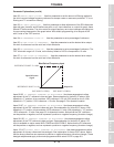
Item 142, DYNAMIC BRAKING SELECTION - Adjust this parameter when attaching a dynamic braking
resistor to the drive for increased stopping ability. A setting of "1" affords no protection for the resistor (use
for over-sized wattages, or for externally-protected resistors). A setting of "2" invokes the drive's braking
resistor protection (drive will trip on DB RESISTOR OVERLOAD if resistor is overloaded). See Items 143
and 144. For optimum use of the dynamic braking resistor, set Item 145, OVERVOLTAGE STALL
PROTECTION to "1", "off".
Item 143, BRAKING RESISTOR VALUE - Enter ohm value of resistor. See page 9-16 for
recommended DBR sizing.
Item 144, BRAKING RESISTOR POWER RATING - Enter kilowatt value of resistor. See page 9-16 for
recommended DBR sizing.
Note:
Items 142, 143, 144 are not applicable to H3 drives above 30 horsepower.