


TOSHIBA
9 - 22
Parameter Explanations (cont'd)
Item 254, PG INPUT: NUMBER OF PHASES - Use this parameter to select either one or two phase
encoder feedback. See the Extended Terminal Block Option Manual for more information.
Item 255, DROOPING CONTROL ENABLE - Use this parameter to enable the H3's load share function,
which continuously stalls based on load. This parameter can be changed while the drive is at a non-zero
output frequency, but the change does not go into effect until drive is stopped.
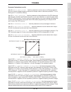
Item 256, DROOPING CONTROL AMOUNT - Use this parameter to set the maximum amount of droop (in
percent of Item 1, MAXIMUM OUTPUT FREQUENCY).
When drooping, Output Frequency = Reference Frequency - Droop
Droop = MAXIMUM OUTPUT FREQUENCY x DROOPING CONTROL AMOUNT x Torque Ratio
Torque Ratio (maximum value of 2.0)= operating torque / rated torque
Item 257, OVERRIDE CONTROL SELECTION - Use this parameter to create a "trim pot". The "trim pot"
function allows a user to uniquely adjust the speed of a drive that is receiving a master reference. The
bias/gain of these inputs determines their effect on the master reference (see Items 84-107). Select which
one of the H3's frequency references will serve as the trim source:
0:
none
1:
"RR" terminal
2:
"IV" terminal
3:
"RX" terminal (+/- trim possible)
4:
Pulse generator input on option card INV3-COM-B or INV3-COM-D (+/- trim possible)
5:
H3 keypad
6:
RS485 input or 12-bit input on option cards INV3-COM-A , INV3-COM-C, or G3-VF5X-4526A
7:
Trim source with multiplier. See Items 258 and 259 below.
Item 258, OVERRIDE MULTIPLIER INPUT SELECTION - When used with a multiplier, the
following inputs' bias and gain do not determine their effect on the master reference. Select which
of the following trim sources will be used with the muliplier:
0:
Frequency reference
1:
"RR" terminal
2:
"IV" terminal
3:
"RX" terminal
4:
RS485 input or 12-bit input on option cards INV3-COM-A, INV3-COM-C, or G3-VF5X-4526A
Item 259, OVERRIDE CHANGE MULTIPLIER - When Item 258 is set to "0", this parameter sets the
percent of reference to be added/subtacted to/from the reference. When Item 258 is set to "1", "2", "3", or
"4", the value entered here determines the maximum range of trim in terms of percentage of reference.
This maximum range of trim includes both positive and negative trim bandwidths. Any amount of trim up to
this maximum is available by changing the trim terminal's input. Maximum negative trim is achieved with
minimum input on trim terminal. Maximum positive trim is achieved with maximum input on trim terminal.
Example: Suppose Item 258 is set to "1" (RR trim), Item 259 is set to "25%", and a 4-20 mA
reference into the "IV" terminal is commanding 40 Hz. When the "RR" input is 0 volts, the drive
outputs 35 Hz (40 - ((40 X 0.25)/2)). When the "RR" input is adjusted to 10 volts, the drive outputs
45 Hz (40 + ((40 X 0.25)/2)).
Item 260, RS232 BAUD RATE - sets baud rate. Cycle power after changing this parameter.
Item 261, NUMBER OF DATA BITS - sets the word length. Cycle power after changing.
Item 262, PARITY SETTING - sets the parity. Cycle power after changing this parameter.
Item 263, INVERTER ID NUMBER - assigns unique ID to drive for use on RS485 net. Cycle power after
changing this parameter.
Specifications
Precautions
Wiring
JumpersPanelKeypadParametersProgrammingServiceDimensionsIndex Inspection