


TOSHIBA
9 - 21
Parameter Explanations (cont'd)
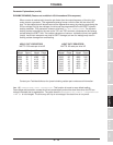
Items 214, 216, 218, 220, 222, 224, 226, 228, 230, 232, 234, 236, 238, 240, and 242, SPEED NUMBER
<1,2,3,4,5,6,7,8,9,10,11,12,13,14, or 15> DRIVE TIME - This parameter determines the
amount of time associated with each
preset
speed. The time unit (minutes/seconds is determined by the
preceding parameter.
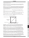
Item 243, FEEDBACK CONTROL SELECTION - This parameter programs the drive to operate in PID
mode (maintain a process variable such as pressure), speed feedback, or in normal mode.
Item 244, FEEDBACK INPUT SIGNAL SELECTION - This parameter programs the drive to accept
feedback at one of many possible inputs:
1:
"RR" terminal
2:
"IV" terminal
3:
"RX" terminal
4:
Pulse generator input (on option board INV3-COM-B or INV3-COM-D)
5:
RS232 port
6:
RS485 port or 12 bit input (on option board INV3-COM-A, INV3-COM-C or
G3-VF5X-4526A
7:
Binary input ( via input terminals programmed appropriately - see Items 45-54 and
setting values 22-32 on page 9-9).
Item 245, PROPORTIONAL GAIN - The larger the value here, the quicker the drive responds to changes
in feedback. Contact Houston for the PID application guideline. READ/WRITE does not have to be
pressed to make the value entered here effective.
Item 246, INTEGRAL GAIN - Also known as reset, this parameter is actually a time. The smaller the
value here, the more pronounced the effect of the integral function. Contact Houston for the PID
application guideline. READ/WRITE does not have to be pressed to make the value entered here
effective.
Item 247, ANTI-HUNTING GAIN - Also known as differential gain or rate, this parameter is actually a
time. The larger the value here, the more pronounced the effect of the differential function. Contact
Houston for the PID application guideline. READ/WRITE does not have to be pressed to make the value
entered here effective.
Item 248, LAG TIME CONSTANT - This parameter effects drive reaction time to change in feedback
value. Decrease this setting to improve drive response.
Item 249, PID LOWER LIMIT FREQUENCY - When PID is active, Item 7, LOWER LIMIT FREQUENCY
is not effective. This parameter is the lower limit when PID is active. Some drives have a version of keypad
ROM that does not contain this parameter (version 100). If drive cannot display this parameter, see
section 7.4 about identifying keypad ROM version. Keypad ROM versions 110 and 121 contain Item 249.
Item 250, PID DEVIATION LIMIT SELECTION - The amount of correction calculated by the drive can
be limited to control possible system oscillations. Place a "1" here to PID deviation limit.
Item 251, PID DEVIATION UPPER LIMIT - The amount of correction calculated by the drive is limited
to the value entered here, expressed in terms of percent of Item 1, MAXIMUM OUTPUT FREQUENCY.
Item 252, PID DEVIATION LOWER LIMIT - The amount of correction calculated by the drive is limited
to the value entered here, expressed in terms of percent of Item 1, MAXIMUM OUTPUT FREQUENCY.
Item 253, PG INPUT: NUMBER OF PULSES - When an encoder and PG option board (INV3-COM-B or
INV3-COM-D) is being used for closed loop speed control, enter pulses per revolution. When using option
board to follow a pulse reference, enter number of pulses that correspond to a frequency command of one
hertz. See the Extended Terminal Block Option Manual for more information.