


TOSHIBA
9 - 14
Parameter Explanations (cont'd)
Item 82, ANALOG INPUT FILTER - Use this parameter to set the amount of filtering applied to
the drive's current/voltage frequency reference to dampen noise or resonance problems. "0" is no
filtering and "3" is maximum filtering.
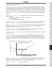
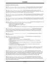
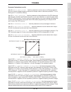
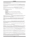
Item 83, RR INPUT SELECTION - Use this parameter to allow adjustment of the RR reference's
bias and gain. Items 84 and 85 define one point on a % input reference vs. output Hz graph; Items
86 and 87 define another. The drive varies its output frequency as its input changes according to a
line connecting these points. See graph below. With default programming, drive outputs 40 Hz
with 5 volts on the "RR" terminal.
Item 84, RR REFERENCE POINT #1 - Use this parameter to set a percentage of reference.
Item 85, RR REF POINT #1 FREQUENCY - Use this parameter to set the desired drive output
Hz when its reference has the value set in Item 84 above.
Item 86, RR REFERENCE POINT #2 - Use this parameter to set a percentage of reference. The
"RR" terminal's range is 0-10 volts, so the factory default of 100% corresponds to 10 volts.
Item 87, RR REF POINT #2 FREQUENCY - Use this parameter to set the desired drive output
Hz when its reference has the value set in Item 86 above.
Items 88-92, IV TERMINAL STANDARD OR ADJUSTABLE - Use these parameters to allow
adjustment of the "IV" reference's bias and gain. See explanation for Items 83-87 above. With
dipswitch in "I" position, drive considers 100% reference = 20 mA (20% would be 4 mA). With
dipswitch in "V" position, 100% reference = 10 volts. See page 5-3 for dipswitch location.
Items 93-97, RX TERMINAL STANDARD OR ADJUSTABLE - Use these parameters to allow
adjustment of the "RX" reference's bias and gain. See explanation for Items 83-87 above. With
dipswitch in "5" position, drive considers 100% reference = 5 volts. With dipswitch in "10" position,
100% reference = 10 volts. See page 5-3 for dipswitch location. Notice that the "RX" reference
can be positive or negative, and can represent a positive or negative frequency (direction change).
Items 98-102, PG TERMINAL STANDARD OR ADJUSTABLE - Use these parameters to allow
adjustment of the "PG" reference's bias and gain. See explanation for Items 83-87 above. PG
input is available on option cards INV3-COM-B and INV3-COM-D. Notice that the PG reference
can be positive or negative, and can represent a positive or negative frequency (direction change).
Items 103-107, BINARY INPUT STANDARD OR ADJUSTABLE - Use these parameters to allow
adjustment of a binary reference's bias and gain. See explanation for Items 83-87 above. Notice
that the binary reference can represent a positive or negative frequency (direction change). These
bias/gain adjustments apply to terminals programmed with values 22-32 on page 9-9.
REF POINT #2 FREQREF POINT #1 FREQ
Bias/Gain of Frequency Input
REFERENCE POINT #2: 100%
REFERENCE POINT #1: 0%
Output Hz
80 Hz0 Hz
Input Reference
Signal
Specifications
Precautions
Wiring
JumpersPanelKeypadParametersProgrammingServiceDimensionsIndex Inspection