


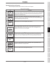
TOSHIBA
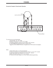
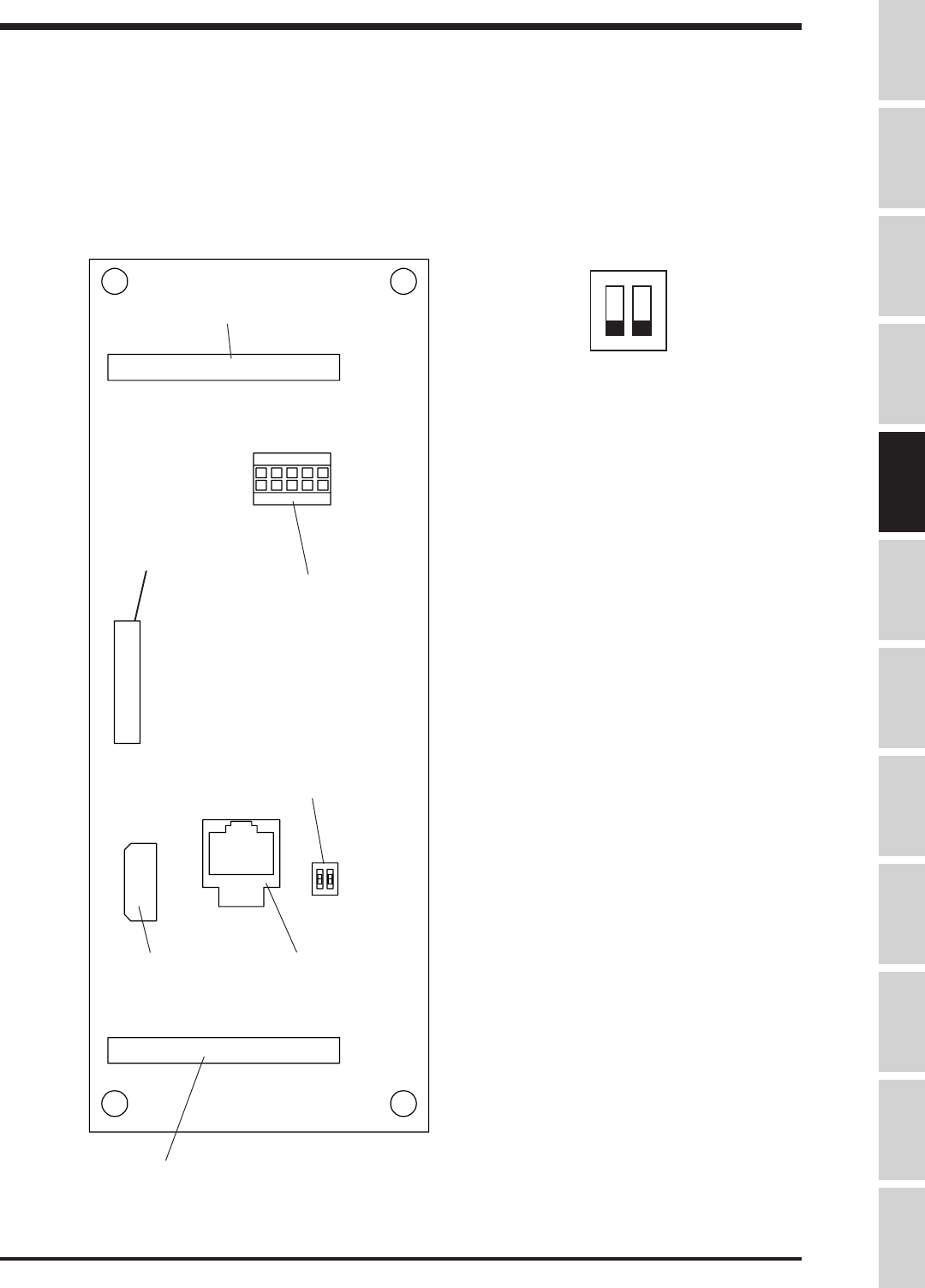
Control Board
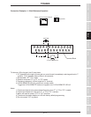
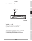
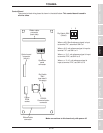
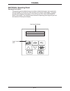
The control printed wiring board is shown in the detail below. This control board is used in
all drive sizes.
5 - 2
RS-232
Communication
connector
Dip Switch
SW1
(see detail 1
this page)
I5
10V
Option
ROM
socket
Operation
panel
connector
Option board
connector
(40-pin)
Ribbon cable
connector
Ribbon cable
connector
(back side)
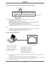
Dip Switch SW1
(Detail)
When a 4(0)-20mA reference signal is input
to terminal "IV", set switch SW1 to I
When a 0-10 volt reference signal is input to
terminal "IV", set SW1 to V
When a +/- 0-5 volt reference signal is input
to terminal "RX", set SW1 to 5
When a +/- 0-10 volt reference signal is
input to terminal "RX", set SW1 to 10
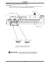
Make connections to this board only with power off.
Specifications
Precautions
Wiring
JumpersPanelKeypadParametersProgrammingServiceDimensionsIndex Inspection