


TOSHIBA
9 - 23
Parameter Explanations (cont'd)
Item 264, COMMUNICATION SELECTION - Use this parameter to select type of communication:
0:
None
1:
RS485 port on option boards INV3-COM-A, INV3-COM-C, or INV3-COM-B
2:
Toshiba TOSLINE F10 (twisted pair). Contact your Toshiba distributor for more information
3:
Toshiba TOSLINE S20 (fiber optic). Contact your Toshiba distributor for more information.
4:
12 bit binary reference using option card G3-VF5X-4526A
5:
Three digit BCD input on card G3-VF5X-4526A ( 0.1 Hz resolution )
6:
Three digit BCD input on card G3-VF5X-4526A ( 1.0 Hz resolution )
Cycle power after changing this parameter.
Item 265, MASTER/SLAVE SELECTION - This parameter defines the drive's role in the master/
follower scenario. A value of "1" entered here will make followers follow the frequency command
the master is receiving (master may be stopped while the followers run). A value of "2" entered
here will make the followers run according to the master's output frequency. Cycle power after
changing this parameter.
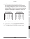
Item 266, RS485 BAUD RATE - In conjunction with jumpers J1 ands J2 on the RS485 option
board used, this parameter sets the
RS485 baud rate
as follows:
Position of Setting of Item 266
J1 J2 0 1
off off
9600 38400
on off
4800 19200
off on
2400 9600
on on
1200 4800
INV3-COM-A and INV3-COM-B cards' max baud is 19200.
INV3-COM-C card's max baud is 38400.
Cycle power after changing this parameter.
Item 267, TOSLINE F10/S20 COMMAND INPUT - determines if drive accepts run/stop and/or
frequency commands from TOSLINE. Contact PLC marketing for more information. Cycle power
after changing this parameter.
Item 268, TOSLINE F10/S20 MONITOR OUTPUT - determines the drive operating data to be
communicated. Contact PLC marketing for more information. Cycle power after changing this
parameter.
Item 269, TOSLINE F10/S20 COMM ERROR MODE - When set to a value of "0", a zero speed
command is commenced in the event of an error. A value of "1" the data prior to the error is held.
Cycle power after changing this parameter.
Items 270-274 , RS485/12-BIT BINARY BIAS, GAIN - use these parameters to allow
adjustment of the RS485 or 12 bit reference's bias and gain. See explanation for Items 83-87
above. Follower's 100% reference is master's Item 1, MAXIMUM OUTPUT FREQUENCY. RS485 input is
available on option cards INV3-COM-A, INV3-COM-B, and INV3-COM-C. 12 bit binary input is available
on option card G3-VF5X-4526A. Cycle power after changing this parameter.
Item 275, FM TERMINAL FUNCTION SELECTION - This parameter determines the drive
operating variable associated with the 0-1 mA/4-20 mA signal from the "FM" and "CC" terminals.
The "FM" output is user-selected as 0-1 mA or 4-20 mA by setting JP3 (to the left of the terminal
strip) in the appropriate position (see page 5-2).
Do not make connections to this terminal with the
drive powered.
(continued next page)