


TOSHIBA
9 - 27
Parameter Explanations (cont'd)
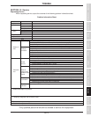
Items 289-292, STATUS MONITOR #<1,2,3,and 4> SELECT - Pressing MON button displays the drive's
monitor mode. See Item 296 to display currents in amps or percent. See Item 297 to display voltages in
volts or percent. The drive operation variable displayed in four of the monitor mode's screens are
selectable:
1:
Post-compensation output frequency may be higher than frequency command (drive
overspeeds to compensate for slip in vector control).
2:
Frequency command.
Not affected by stopping or accel/decel.
Default for STATUS MONITOR #1 DISPLAY SELECT
3:
Output current. (output amps)
2
=(torque amps)
2
+(excitation amps)
2
Default for STATUS MONITOR #2 DISPLAY SELECT
4:
Input voltage (calculated from DC bus voltage). If displayed in percent, note that 230 V drives
consider 200 V to be 100% input and 460 V drives consider 400 V to be 100% input.
Default for STATUS MONITOR #3 DISPLAY SELECT
5:
Output voltage. If displayed in percent, note that 230 V drives consider 200 V to be 100% output
and 460 V drives consider 400 V to be 100% output.
Default for STATUS MONITOR #4 DISPLAY SELECT
6:
Torque current. (output current)
2
= (torque current)
2
+ (excitation current)
2
7:
Excitation current.
(output current)
2
= (torque current)
2
+ (excitation current)
2
8:
PID feedback value. This is the frequency represented by the feedback signal
9:
Motor overload ratio. Example: H3 is rated for 150% FLA for 2 minutes. If drive runs at 150%
for one minute, this output will be 50%. Drive trips when ration hits 100%.
10:
Inverter overload ratio. See example for selection 9 above.
11:
Dynamic braking resistor overload ratio. See example for selection 9 above.
12:
Input power
13:
Output power
14:
"RR" terminal input value (the variable displayed here varies with the setting of Item 79, RR
INPUT SPECIAL FUNCTION SELECT).
15:
Peak output current. Peak is reset by cycling power, initiating a run, or resetting drive.
16:
Peak input voltage. Peak is reset by cycling power, initiating run, or resetting drive.
Calculated from DC bus. If displayed in percent, note that 230 V drives consider 200 V input to
be 100% and that 460 drives consider 400 V input to be 100%.
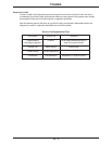
Item 293, FREQUENCY UNITS SCALE FACTOR - Drive's frequency output display can be scaled by
putting a non-zero value here. Drive's display will still read OUTPUT FREQUENCY, but HZ will no longer be
visible.
Item 294, FREQUENCY DISPLAY RESOLUTION - Use this parameter to select the number of decimal
points for keypad's output frequency display.
Item 295, ACC/DEC TIME UNITS SELECTION - Affects Items 10,11,21, and 22 (sets resolution of
accel/decel times).
Item 296, CURRENT UNITS SELECTION - With this parameter set to "1", drive displays currents in amps.
Item 297, VOLTAGE UNITS SELECTION - With this parameter set to "0", the voltages displayed in the
monitor are in percent.
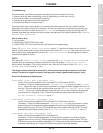
Item 298, BLIND FUNCTION SELECTION - Page 8-31 contains the parameters that unblind the H3's
programming groups. Item 298 must be set to "1" before Items 299-315 can be read or changed.
Item 299, FUNDAMENTAL PARAMS #2 BLIND - This parameter must be set to "1" before any of the
parameters on page 8-2 can be read or changed. Putting a "1" here adds GROUP: FUNDAMENTAL
PARAMETERS #1 to the group list (accessed via the PRG button).