


TOSHIBA
9 - 5
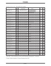
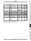
Parameter Explanations (cont'd)
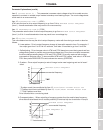
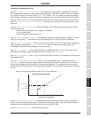
Item 13, ACCEL/DECEL PATTERN ADJUST LOW - expressed as a percentage of Item 10, this time is
represented as "*" in the graph of S Pattern for Item 12.
Item 14, ACCEL/DECEL PATTERN ADJUST HIGH - expressed as a percentage of Item 10, this time is
represented as "**" in the graph of S Pattern for Item 12.
Note for GROUP:FUNDAMENTAL PARAMETERS #2
The parameters in this group are similar to those found in GROUP: FUNDAMENTAL PARAMETERS #1.
These two groups allow the user to program the drive for operation with two different motors (only one
motor connected to drive at a time). The user can determine if GROUP: FUNDAMENTAL PARAMETERS #1
or if GROUP: FUNDAMENTAL PARAMETERS #2 is active by setting Item 27, FUNDAMENTAL PARAM
SWITCHING as desired or by setting one of the drive's input terminal's function to "12" and opening/closing
that terminal to the CC terminal. The user can also determine if ACCELERATION TIME #1/DECELERA-
TION TIME #1 or ACCELERATION TIME #2/DECELERATION TIME #2 is active by setting Item 28,
ACCEL/DECEL #1/#2 SELECTION or by setting one of the drive's input terminal's functions to "9" and
opening/closing that terminal to the CC terminal. See page 9-7 for more information on programming the
input terminals.
Item 15, BASE FREQUENCY #2 - see item 2, BASE FREQUENCY #1
Item 16, MAXIMUM OUTPUT VOLTAGE #2 - see item 4, MAXIMUM OUTPUT VOLTAGE #1
Item 17, VOLTAGE BOOST #2 - see item 9, VOLTAGE BOOST #1
Item 18, ELECTRONIC THERMAL PROTECT LEVEL #2 - This parameter lowers the drive's overload to
protect the motor. Divide motor full-load amps by drive full-load amps and multiply by one hundred. Enter
the result in this parameter. Input in amps with item 296, CURRENT UNITS SELECTION, is set to "1".
Item 19, STALL PROTECTION SELECTION #2 - Stall is a drive function wherein the drive limits the
motor current by reducing output voltage and frequency in an effort to reduce load. Stall is most effective
on variable torque loads. This parameter turns stall off/on.
Item 20, STALL PROTECTION LEVEL #2 - Enter the current limit in amps or in percent of drive rating.
See Item 296, CURRENT UNITS SELECTION, to change units from % to amps.
Item 21, ACCELERATION TIME #2 - see item 10, ACCELERATION TIME #1
Item 22, DECELERATION TIME #2 - see item 11, DECELERATION TIME #1
Item 23, ACC/DEC PATTERN #2 SELECTION - see item 12, ACC/DEC PATTERN #1 SELECTION
Item 24, ACC/DEC #1/#2 SWITCHING FREQUENCY - The drive can be programmed to switch from
accel/decel time #1 to accel/decel time #2 based on output frequency. Enter the Hz at which the drive
should switch from accel/decel time #1 to accel/decel time #2.
Item 25, DIRECTION SELECTION (FORWARD/REVERSE) - This parameter determines direction when
commanding start/stop from keypad. Direction can also be changed from the keypad by pressing READ/
WRITE and the up or down arrow simultaneously (with Item 25 set to "1").
Item 26, STOP PATTERN SELECTION - This parameter determines whether the drive follows the decel
curve when the STOP button is pressed or if it performs a coast-stop. Coast stop is also performed when
ST-CC is broken.
Item 27, FUNDAMENTAL PARAM SWITCHING - This parameter determines whether GROUP:
FUNDAMENTAL PARAMETERS #1 or GROUP:FUNDAMENTAL PARAMETERS #2 is used.