4.10 Display Assembly 4 Replacement Procedures
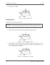
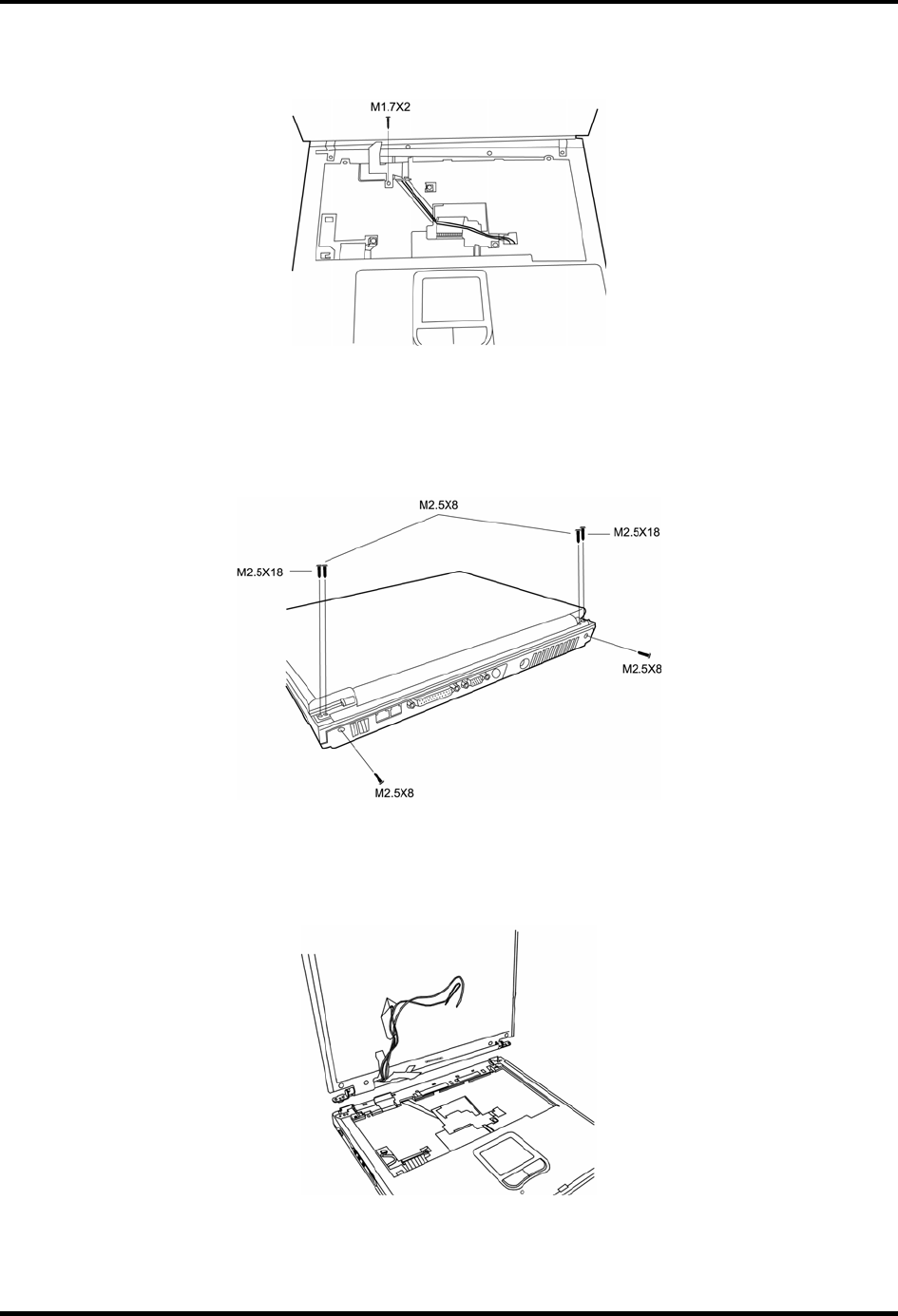
4. Remove one M1.7x2 black screws connecting the LCD cable to the chassis.
Figure 4-41 Detaching the LCD cable
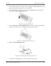
5. From each top corner, remove: one M2.5x18 black screw (outer) and one M2.5x8 black
screw (inner). From each back corner, remove: one M2.5x8 black screw. There are a
total of three screws for each corner, and six screws for the whole display assembly.
Figure 4-42 Removing the bracket screws
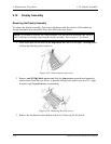
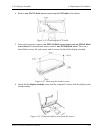
6. Gently lift the display assembly away from the computer’s chassis with the display in the
closed position.
Figure 4-43 Lifting the display away from the chassis
Satellite A30 Series Maintenance Manual 4-27


