


BLADEOS 6.5.2 Application Guide
104 Chapter 7: Ports and Trunking BMD00220, October 2010
Trunk Group Configuration Rules
The trunking feature operates according to specific configuration rules. When creating trunks,
consider the following rules that determine how a trunk group reacts in any network topology:
All trunks must originate from one device, and lead to one destination device.
Any physical switch port can belong to only one trunk group.
Trunking from third-party devices must comply with Cisco
®
EtherChannel
®
technology.
All ports in a trunk must have the same link configuration (speed, duplex, flow control), the
same VLAN properties, and the same Spanning Tree, storm control, and ACL configuration. It
is recommended that the ports in a trunk be members of the same VLAN.
Each trunk inherits its port configuration (speed, flow control, tagging) from the first member
port. As additional ports are added to the trunk, their settings must be changed to match the
trunk configuration.
When a port leaves a trunk, its configuration parameters are retained.
You cannot configure a trunk member as a monitor port in a port-mirroring configuration.
Trunks cannot be monitored by a monitor port; however, trunk members can be monitored.
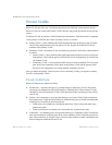
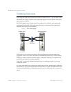
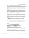
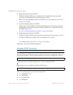
Port Trunking Example
In the example below, three ports are trunked between two switches.
Figure 8 Port Trunk Group Configuration Example
Prior to configuring each switch in the above example, you must connect to the appropriate
switches as the administrator.
Note – For details about accessing and using any of the commands described in this example, see
the RackSwitch G8124 ISCLI Reference.
Trunk 3: Ports 2, 9, and 16
Trunk 1: Ports 1, 11, and 18
9 10 11 125 6 7 8
Stacking
SP
L/A
MB
MS
17 18 19 2013 14 15 16 21 22 23 24 Mgmt
B
A
BLADE
Rackswitch G8124
1 2 3 4
10101 Reset
9 10 11 125 6 7 8
Stacking
SP
L/A
MB
MS
17 18 19 2013 14 15 16 21 22 23 24 Mgmt
B
A
BLADE
Rackswitch G8124
1 2 3 4
10101 Reset
92
16
18111