


BLADEOS 6.5.2 Application Guide
96 Chapter 6: VLANs BMD00220, October 2010
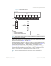
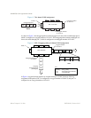
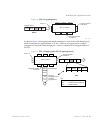
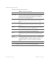
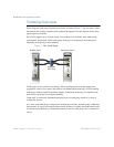
The features of this VLAN are described below:
Note – VLAN tagging is required only on ports that are connected to other switches or on ports that
connect to tag-capable end-stations, such as servers with VLAN-tagging adapters.
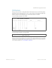
Table 6-1 Multiple VLANs Example
Component Description
G8124 switch This switch is configured with three VLANs that represent three different IP
subnets. Five ports are connected downstream to servers. Two ports are
connected upstream to routing switches. Uplink ports are members of all
three VLANs, with VLAN tagging enabled.
Server 1 This server is a member of VLAN 1 and has presence in only one IP subnet.
The associated switch port is only a member of VLAN 1, so tagging is
disabled.
Server 2 This server is a member of VLAN 1 and has presence in only one IP subnet.
The associated switch port is only a member of VLAN 1, so tagging is
disabled.
Server 3 This server belongs to VLAN 2, and it is logically in the same IP subnet as
Server 5. The associated switch port has tagging disabled.
Server 4 A member of VLAN 3, this server can communicate only with other servers
via a router. The associated switch port has tagging disabled.
Server 5 A member of VLAN 1 and VLAN 2, this server can communicate only with
Server 1, Server 2, and Server 3. The associated switch port has tagging
enabled.
Enterprise
Routing switches
These switches must have all three VLANs (VLAN 1, 2, 3) configured. They
can communicate with Server 1, Server 2, and Server 5 via VLAN 1. They
can communicate with Server 3 and Server 5 via VLAN 2. They can
communicate with Server 4 via VLAN 3. Tagging on switch ports is
enabled.