


BLADEOS 6.5.2 Application Guide
BMD00220, October 2010 Chapter 8: Spanning Tree Protocols 111
STP/PVST+ Mode
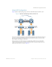
Using STP, network devices detect and eliminate logical loops in a bridged or switched network.
When multiple paths exist, Spanning Tree configures the network so that a switch uses only the
most efficient path. If that path fails, Spanning Tree automatically sets up another active path on the
network to sustain network operations.
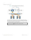
BLADEOS STP/PVST+ mode implements IEEE 802.1D (1998) Spanning Tree Protocol (STP)
with enhancements that allow each VLAN to be assigned to one of 127 available STGs.
STP/PVST+ uses IEEE 802.1Q for tagging STP data on a per-VLAN basis, and is compatible with
Cisco PVST+ mode. For Cisco R-PVST/R-PVST+ compatibility, see “Per-VLAN Rapid Spanning
Tree Groups” on page 126).
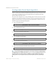
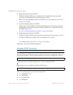
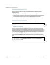
The relationship between ports, trunk groups, VLANs, and Spanning Trees is shown in Table 11.
Port States
STP/PVRST+ mode employs a sequence of port states in the process: Listening, Learning, and
Forwarding or Blocking. This process can result in inherent delays for resolving network paths.
To mitigate delays, you can use Port Fast Forwarding (see “Port Fast Forwarding” on page 114) to
permit a port that participates in STP/PVST+ to bypass the Listening and Learning states and enter
directly into the Forwarding state. While in the Forwarding state, the port listens to the BPDUs to
learn if there is a loop and, if dictated by normal STG behavior (following priorities, and so on), the
port transitions into the Blocking state.
This feature permits the G8124 to interoperate well within Rapid Spanning Tree networks.
Table 11 Ports, Trunk Groups, and VLANs
Switch Element Belongs To
Port Trunk group,
or one or more VLANs
Trunk group One or more VLANs
VLAN (non-default) One VLAN per STG,
or in enhanced modes:
RSTP: All VLANs are in STG 1
PVRST: One VLAN per STG
MSTP: Multiple VLANs per STG