


BLADEOS 6.5.2 Application Guide
220 Chapter 15: Basic IP Routing BMD00220, October 2010
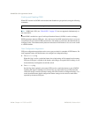
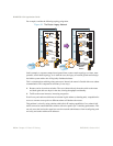
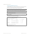
For example, consider the following topology migration:
Figure 24 The Router Legacy Network
In this example, a corporate campus has migrated from a router-centric topology to a faster, more
powerful, switch-based topology. As is often the case, the legacy of network growth and redesign
has left the system with a mix of illogically distributed subnets.
This is a situation that switching alone cannot cure. Instead, the router is flooded with cross-subnet
communication. This compromises efficiency in two ways:
Routers can be slower than switches. The cross-subnet side trip from the switch to the router
and back again adds two hops for the data, slowing throughput considerably.
Traffic to the router increases, increasing congestion.
Even if every end-station could be moved to better logical subnets (a daunting task), competition for
access to common server pools on different subnets still burdens the routers.
This problem is solved by using switches with built-in IP routing capabilities. Cross-subnet LAN
traffic can now be routed within the switches with wire speed Layer 2 switching performance. This
not only eases the load on the router but saves the network administrators from reconfiguring each
and every end-station with new IP addresses.
Internet
Internet
Internet
Internet
BLADE
Switch
Server
Subnet
Server
Subnet