


BLADEOS 6.5.2 Application Guide
130 Chapter 8: Spanning Tree Protocols BMD00220, October 2010
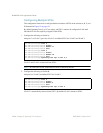
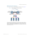
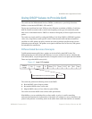
1. Configure port membership and define the STGs for VLAN 1. Enable tagging on uplink ports that
share VLANs. Port 19 and port 20 connect to the Enterprise Routing switches.
2. Add server ports 1 and 2 to VLAN 1. Add uplink ports 19 and port 20 to VLAN 1.
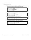
3. Configure MSTP: Spanning Tree mode, region name, and version.
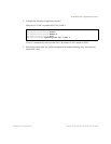
4. Configure port membership and define the STGs for VLAN 2. Add server ports 3, 4, and 5 to
VLAN 2. Add uplink ports 19 and 20 to VLAN 2. Assign VLAN 2 to STG 2.
Note – Each STG is enabled by default.
RS G8124(config)# interface port 19
RS G8124(config-if)# tagging
RS G8124(config-if)# exit
RS G8124(config)# interface port 20
RS G8124(config-if)# tagging
RS G8124(config-if)# exit
RS G8124(config)# vlan 1
RS G8124(config-vlan)# enable
RS G8124(config-vlan)# member 1,2,19,20
RS G8124(config-vlan)# stg 1
RS G8124(config-vlan)# exit
RS G8124(config)# spanning-tree mstp name MyRegion
RS G8124(config)# spanning-tree mode mst
RS G8124(config)# spanning-tree mstp version 100
RS G8124(config)# vlan 2
RS G8124(config-vlan)# enable
RS G8124(config-vlan)# member 3,4,5,19,20
RS G8124(config-vlan)# stg 2
RS G8124(config-vlan)# exit