


BLADEOS 6.5.2 Application Guide
BMD00220, October 2010 Chapter 12: Virtual NICs 161
vNIC Configuration Example
Consider the following example configuration:
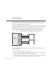
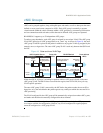
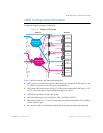
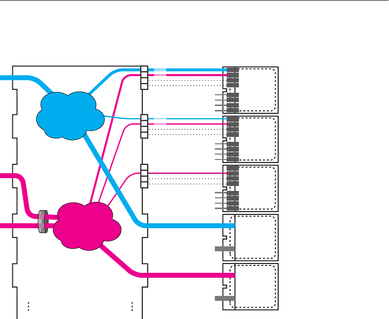
Figure 21 Multiple vNIC Groups
Figure 21 has the following vNIC network characteristics:
vNIC group 1 has an outer tag for VLAN 1000. The group is comprised of vNIC pipes 1.1 and
2.1, switch server port 4 (a non-vNIC port), and uplink port 11.
vNIC group 2 has an outer tag for VLAN 1774. The group is comprised of vNIC pipes 1.2, 2.2
and 3.2, switch server port 5, and an uplink trunk of ports 13 and 14.
vNIC failover is enabled for both vNIC groups.
vNIC bandwidth on port 1 is set to 60% for vNIC 1 and 40% for vNIC 2.
Other enabled vNICs (2.1, 2.2, and 3.2) are permitted the default bandwidth of 25% (2.5Gbsp)
on their respective ports.
All remaining vNICs are disabled (by default) and are automatically allocated 0 bandwidth.
OS or
Hypervisor
VNIC
VNIC
VNIC
VNIC
VNIC
VNIC
VNIC
VNIC
OS or
Hypervisor
VNIC
VNIC
VNIC
VNIC
VNIC
VNIC
VNIC
VNIC
OS or
Hypervisor
VNIC
VNIC
VNIC
VNIC
VNIC
VNIC
VNIC
VNIC
OS or
Hypervisor
OS or
Hypervisor
Switch 1 Servers
To Switch 2
To Switch 2
To Switch 2
To Switch 2
To Switch 2
Port
11
Port
12
Port
13
Port
14
Port
15
Port
1
Port
2
Port
3
Port
4
Port
5
.1
.2
.3
.4
.1
.2
.3
.4
.1
.2
.3
.4
60%
40%
25%
25%
25%
VNIC Group 1
VLAN 1000
VNIC Group 2
VLAN 1774