


BLADEOS 6.5.2 Application Guide
92 Chapter 6: VLANs BMD00220, October 2010
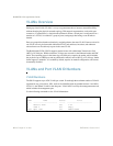
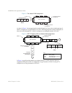
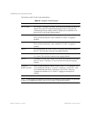
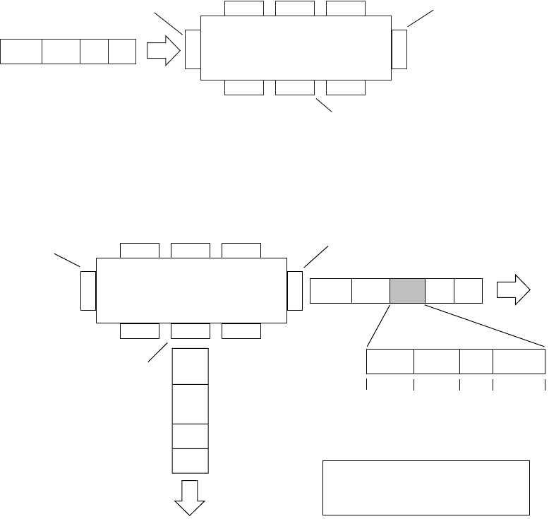
Figure 2 Port-based VLAN assignment
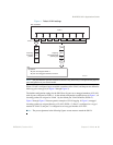
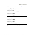
As shown in Figure 3, the untagged packet is marked (tagged) as it leaves the switch through port 5,
which is configured as a tagged member of VLAN 2. The untagged packet remains unchanged as it
leaves the switch through port 7, which is configured as an untagged member of VLAN 2.
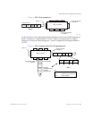
Figure 3 802.1Q tagging (after port-based VLAN assignment)
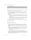
In Figure 4, tagged incoming packets are assigned directly to VLAN 2 because of the tag
assignment in the packet. Port 5 is configured as a tagged member of VLAN 2, and port 7 is
configured as an untagged member of VLAN 2.
Port 6
DASADataCRC
Port 7 Port 8
Port 1
Port 4
Port 5
Port 2 Port 3
802.1Q Switch
PVID = 2
Untagged packet
Untagged member
of VLAN 2
Tagged member
of VLAN 2
B
e
f
o
r
e
Port 6 Port 7 Port 8
Port 1
Port 4
Port 5
Port 2 Port 3
802.1Q Switch
Key
Priority
CFI
VID
- User_priority
- Canonical format indicator
- VLAN identifier
PVID = 2
Tagged member
of VLAN 2
Untagged memeber
of VLAN 2
After
DA
SA
Data
CRC
(*Recalculated)
Outgoing
untagged packet
(unchanged)
DASADataCRC* Tag
VID = 2Priority
16 bits 3 bits 1 bits 12 bits
8100 CFI