


BLADEOS 6.5.2 Application Guide
BMD00220, October 2010 Chapter 14: FCoE and CEE 209
If PGID 15 has low traffic levels, most of the switch’s bandwidth will be available to serve priority
groups 0 through 7. However, if PGID 15 consumes a larger part of the switch’s total bandwidth,
the amount available to the other groups is reduced.
Note – Consider traffic load when assigning priority values to PGID 15. Heavy traffic in this group
may restrict the bandwidth available to other groups.
Configuring ETS
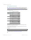
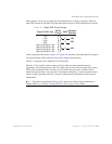
Consider an example consistent with that used for port-based PFC configuration (on page 202):
The example shown in Table 19 is only slightly different than the default configuration shown in
Figure 23 on page 205. In this example, latency-sensitive LAN traffic (802.1p priority 5 through 6)
are moved from priority group 4 to priority group 5. This leaves Business Critical LAN traffic
(802.1p priority 4) in priority group 4 by itself. Also, a new group for network management traffic
has been assigned. Finally, the bandwidth allocation for priority groups 3, 4, and 5 are revised.
Note – DCBX may be configured to permit sharing or learning PFC configuration with or from
external devices. This example assumes that PFC configuration is being performed manually. See
“Data Center Bridging Capability Exchange” on page 211 for more information on DCBX.
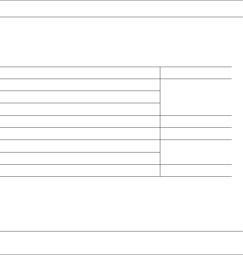
Table 19 ETS Configuration
Priority Usage PGID Bandwidth
0 LAN (best effort delivery)
2 10%1 LAN (best effort delivery)
2 LAN (best effort delivery)
3 SAN (Fibre Channel over Ethernet, with PFC) 3 20%
4 Business Critical LAN (lossless Ethernet, with PFC) 4 30%
5 Latency-sensitive LAN
5 40%
6 Latency-sensitive LAN
7 Network Management (strict) 15 unlimited