


4-24
4
Service Procedures
TO REMOVE BOARDS AND CABLES FROM THE MOTHERBOARD
1. Shut down and open the ColorPASS (see page 4-4 and page 4-5).
2. Remove the front panel (see page 4-8).
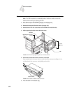
3. Remove the following board(s) from the motherboard:
• Copier interface board in motherboard connector PCI2 (see page 4-18)
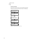
To remove a board, remove its mounting bracket screw(s), grasp the board at the front
and back edge and gently pull it straight out of its connector on the motherboard.
Place each board on an antistatic surface.
Remove any other option boards that may be installed in remaining connectors on the
motherboard.
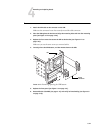
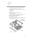
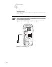
4. Remove the plastic cable clamp securing internal cables.
Set the cable clamp aside for use later.
5. Remove the power and ribbon cables from the back of the HDD.
You need to remove these cables to provide clearance for removing the motherboard.
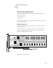
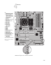
6. Remove the following cables connected to the motherboard:
•Front panel fan cable (FAN3)
•Reset button cable (J22)
•Power button cable (J22)
•Speaker cable (J36)
• HDD ribbon cable (PRI_IDE)
•DVD drive ribbon cable (SEC_IDE)
• UIB ribbon cable (JP20)
•Motherboard power cable (20-pin, P1)
• CPU power cable (4-pin, P2)
For motherboard connector locations, see Figure 4-15 on page 4-23.