


4-28
4
Service Procedures
TO REPLACE BOARDS AND CABLES
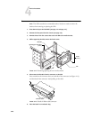
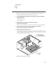
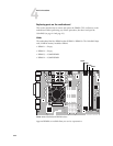
1. Replace the following cables to the motherboard:
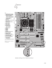
• CPU power cable (4-pin, P2)
• Motherboard power cable (20-pin, P1)
• UIB ribbon cable (JP20)
•DVD drive ribbon cable (SEC_IDE)
• HDD ribbon cable (PRI_IDE)
NOTE: The HDD ribbon cable has two sections. Make sure to connect the longer section
of the cable to the motherboard and the shorter section to the HDD. Also, make sure not
to switch the DVD drive and HDD ribbon cables. The DVD drive ribbon cable has 40
wires; the HDD ribbon cable has 80 wires.
•Speaker cable (J36)
NOTE: Match the small triangle on the speaker cable connector with Pin-1 on
motherboard connector J36 (top most pin; see Figure 4-15 on page 4-23).
•Power and reset button cables (J22; see detail in Figure 4-15 on page 4-23)
•Front panel fan cable (FAN3)
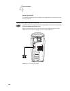
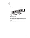
2. Replace the power and ribbon cables to the backs of the HDD and DVD drive.
3. Secure the ribbon cables and the HDD and DVD drive power cables with the plastic cable
clamp you removed earlier.
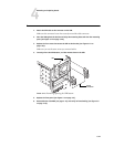
4. Replace the following board in its motherboard connector:
• Copier interface board in motherboard connector PCI2 (see page 4-18)
NOTE: When installing boards, make sure that the board connectors are properly aligned
with their connectors on the motherboard.
5. Make sure all board mounting bracket screws for boards occupying back panel slots are
secured. Press down firmly on the top of the board as you insert each screw.
N
OTE: Make sure unused slots have slot covers installed. Uncovered slots reduce the air
flow and could cause the ColorPASS to overheat.
6. Reassemble the ColorPASS (see page 4-14).
7. If you reinstalled the old motherboard, verify functionality (see page 4-16).
8. If you replaced the motherboard with a new motherboard, proceed to “Verifying new
motherboard installation and updating the system” on page 4-29.