


10-4
Catalyst 2950 and Catalyst 2955 Switch Software Configuration Guide
OL-10101-02
Chapter 10 Configuring Interface Characteristics
Using the Interface Command
When you configure an EtherChannel, you create a port-channel logical interface and assign an interface
to the EtherChannel. For Layer 2 interfaces, the logical interface is dynamically created. You manually
assign an interface to the EtherChannel by using the channel-group interface configuration command.
This command binds the physical and logical ports together. For more information, see
Chapter 30,
“Configuring EtherChannels.”
Connecting Interfaces
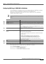
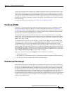
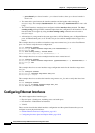
Devices within a single VLAN can communicate directly through any switch. Ports in different VLANs
cannot exchange data without going through a routing device or routed interface.
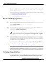
With a standard Layer 2 switch, ports in different VLANs have to exchange information through a router.
In the configuration shown in
Figure 10-1, when Host A in VLAN 20 sends data to Host B in VLAN 30,
it must go from Host A to the switch, to the router, back to the switch, and then to Host B.
Figure 10-1 Connecting VLANs with Layer 2 Switches
Using the Interface Command
To configure a physical interface (port), use the interface global configuration command to enter interface
configuration mode and to specify the interface type, slot, and number.
• Type—Fast Ethernet (fastethernet or fa) for 10/100 Ethernet, Gigabit Ethernet (gigabitethernet or
gi), or LRE (longreachethernet or lo).
• Slot—The slot number on the switch (always 0 on this switch).
• Port number—The interface number on the switch. The port numbers always begin at 1, starting with
the leftmost port when facing the front of the switch, for example, fastethernet0/1, fastethernet0/2.
If there is more than one interface type (for example, 10/100 ports and Gigabit Ethernet ports), the
port number restarts with the second interface type: gigabitethernet0/1, gigabitethernet0/2.
Host A
Switch
Cisco router
VLAN 20
Host B
VLAN 30
46647