


17-5
Catalyst 2950 and Catalyst 2955 Switch Software Configuration Guide
OL-10101-02
Chapter 17 Configuring VTP
Understanding VTP
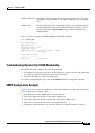
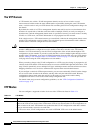
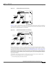
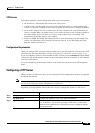
Figure 17-1 Flooding Traffic without VTP Pruning
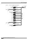
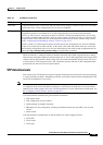
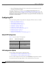
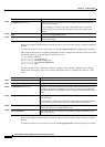
Figure 17-2 shows a switched network with VTP pruning enabled. The broadcast traffic from Switch A
is not forwarded to Switches C, E, and F because traffic for the Red VLAN has been pruned on the links
shown (Port 5 on Switch B and Port 4 on Switch D).
Figure 17-2 Optimized Flooded Traffic with VTP Pruning
Enabling VTP pruning on a VTP server enables pruning for the entire management domain. Making
VLANs pruning-eligible or pruning-ineligible affects pruning eligibility for those VLANs on that device
only (not on all switches in the VTP domain). See the
“Enabling VTP Pruning” section on page 17-14.
VTP pruning takes effect several seconds after you enable it. VTP pruning does not prune traffic from
VLANs that are pruning-ineligible. VLAN 1 and VLANs 1002 to 1005 are always pruning-ineligible;
traffic from these VLANs cannot be pruned. Extended-range VLANs (VLAN IDs higher than 1005) are
also pruning-ineligible.
VTP pruning is not designed to function in VTP transparent mode. If one or more switches in the
network are in VTP transparent mode, you should do one of these:
• Turn off VTP pruning in the entire network.
Switch D
Switch E
Switch CSwitch F Switch A
Switch B
Port 1
Port 2
Red
VLAN
89240
Switch D
Switch E
Switch CSwitch F Switch A
Switch B
Port 1
Port 2
Red
VLAN
89241
Port
4
Flooded traffic
is pruned.
Port
5
Flooded traffic
is pruned.